Mazda 6. Manual - part 9
 

  Index      Mazda     Mazda 6 - service repair manual 2002 year


Search            


Content   ..  7  8  9  10   ..


Mazda 6. Manual - part 9


VALVE MECHANISM 

B–25

B

.

End Of Sie

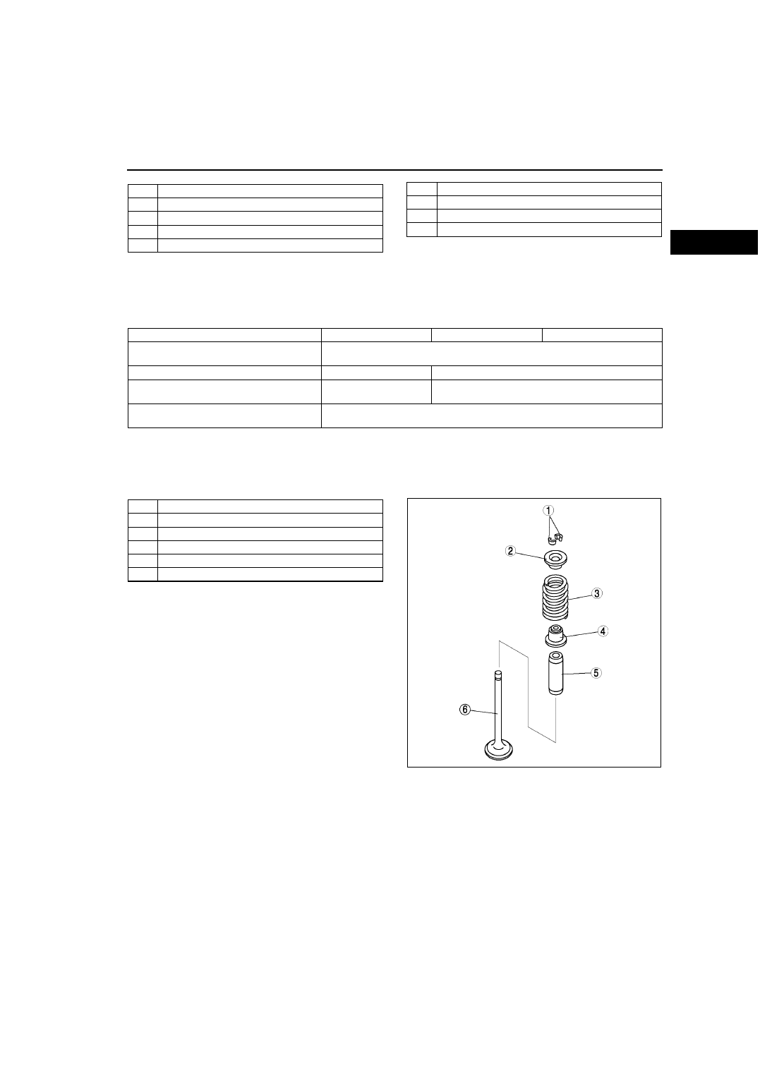
VALVE, VALVE SPRING, VALVE SEAL, VALVE GUIDE

A6E221112111T02

Structure

The valves are heat-resistant steel. There are two intake valves, two exhaust valves per No.1 cylinder.

VALVE SPEC.

The intake valve and the exhaust valve are treated with the tufftride process to improve abrasion resistance.

The valve spring is an uneven outer dimension type. It has been improved by reducing the size of the upper 
seat.

The valve guide is made of the sintered alloy to improve abrasion resistance.

The valve seat is integrated with the lower valve spring seat to simplify the unit and improve its serviceability.

.

End Of Sie

1

Hole for a rachet lock

2

Oil supply hole

3

Check ball

4

Piston spring

5

Piston

6

Rack

7

Ratchet

8

Ratchet spring

9

Cross-section 

ITEM L8

LF

L3 

Valve full length

(mm {in})

Intake valve: About 101.6 {4.000}

Exhaust valve: About102.6 {4.039}

Intake valve umbrella diameter

(mm {in})

About 32.5 {1.28}

About 35 {1.38}

Exhaust valve umbrella diameter  (mm {in})

About 28 

{1.10}

About 30 {1.18}

Stem diameter

(mm {in})

Intake valve: About 5.5 {0.22}

Exhaust valve: About 5.5 {0.22}

1

Valve keeper

2

Upper valve spring seat

3

Valve spring

4

Valve seal

5

Valve guide

6

Valve

AME2211N008

B–26

VALVE MECHANISM 

TAPPET

A6E221112111T03

Structure

The tappet is a shimless tappet which is integrated with the shim.

Besides the tappet, the grounding surface of the cam is phosphate-coated to smooth the surface and improve 
abrasion resistance.

To adjust the valve clearance, replace the tappet. There are 35 kinds of tappets depending on the thickness. 
To distinguish the difference, check the engraved identification mark (3 digits).

Tappet Specification.

.

End Of Sie

Discernment mark

Tappet thickness (mm {in})

The number of jumps (mm {in})

725—625

3.725—3.625 {0.1467—0.1427}

0.025 {0.00098}

602—122

3.602—3.122 {0.1418—0.1229}

0.02 {0.00078}

100—000

3.100—3.000 {0.1220—0.1181}

0.025 {0.00098}

AME2211N007

1

Tappet

2

Camshaft 

3

Tappet sectional view

4

Cam lob contact surface

5

Valve stem contact surface

6

Identification mark position

VALVE MECHANISM 

B–27

B

VALVE MECHANISM

A6E221112111T07

Outline

A variable timing mechanism, which realizes optimum valve timing according to engine operation conditions by 
continuously modifying the phases of the intake camshaft and crankshaft, has been adopted. 

.

Variable Valve Timing Mechanism
Function

The variable valve timing mechanism continuously modifies the phases of the variable valve timing actuator 
and the intake camshaft using hydraulic pressure controlled by the oil control valve (OCV) so that optimal valve 
timing is obtained according to engine operation conditions.

The oil control valve (OCV) operation is based on signals from the PCM according to engine operation 
conditions and it controls hydraulic pressure to the variable valve timing actuator.

Operation and purpose according to driving condition
Idling range, light load range

Due to a reduction in the amount of overlap, less combusted gas is returned to the intake port. This stabilizes 
idle speed in the idling range, improving fuel economy, and also ensures engine stability in the light load range.

Medium load range

Overlap amount has been increased and the EGR ratio inside the cylinder is higher. This reduces engine 
friction loss (pumping loss), lowering the combustion temperature and reducing the amount of NOx the in 
exhaust gas. The amount of hydrocarbon emission has also been reduced through reignition of non-combusted 
gas.

Heavy load, low-middle speed range

The intake valve is closed early, and high volumetric efficiency is obtained to improve low-middle speed torque.

Heavy load, high speed range

Timing for intake valve closure is delayed and high volumetric efficiency is obtained to improve maximum 
output.

When temperature is low

The overlap amount has been minimized to prevent combusted gas from returning to the intake port and to 
reduce the additional fuel injection amount. This improves fuel economy and stabilizes fast idle speed.

AME2211N013

1

Torque

2

Engine speed

3

Low-middle speed engine

4

High speed engine

5

Engine with variable valve timing mechanism

B–28

VALVE MECHANISM 

When engine is started or stopped

Startability has been improved because the overlap amount has been minimized to prevent combusted gas 
from returning to the intake port.

.

AME2211N014

1

Load

2

Engine speed

3

Idling range

4

Light load range

5

Medium load range

6

Heavy load, low-middle speed range

7

Heavy load, high speed range

8

Full load performance


Content   ..  7  8  9  10   ..