Mazda Protege 5. Manual - part 72
ON-BOARD DIAGNOSTIC [ENGINE CONTROL SYSTEM (FS)]
01–02B–108
End Of Sie
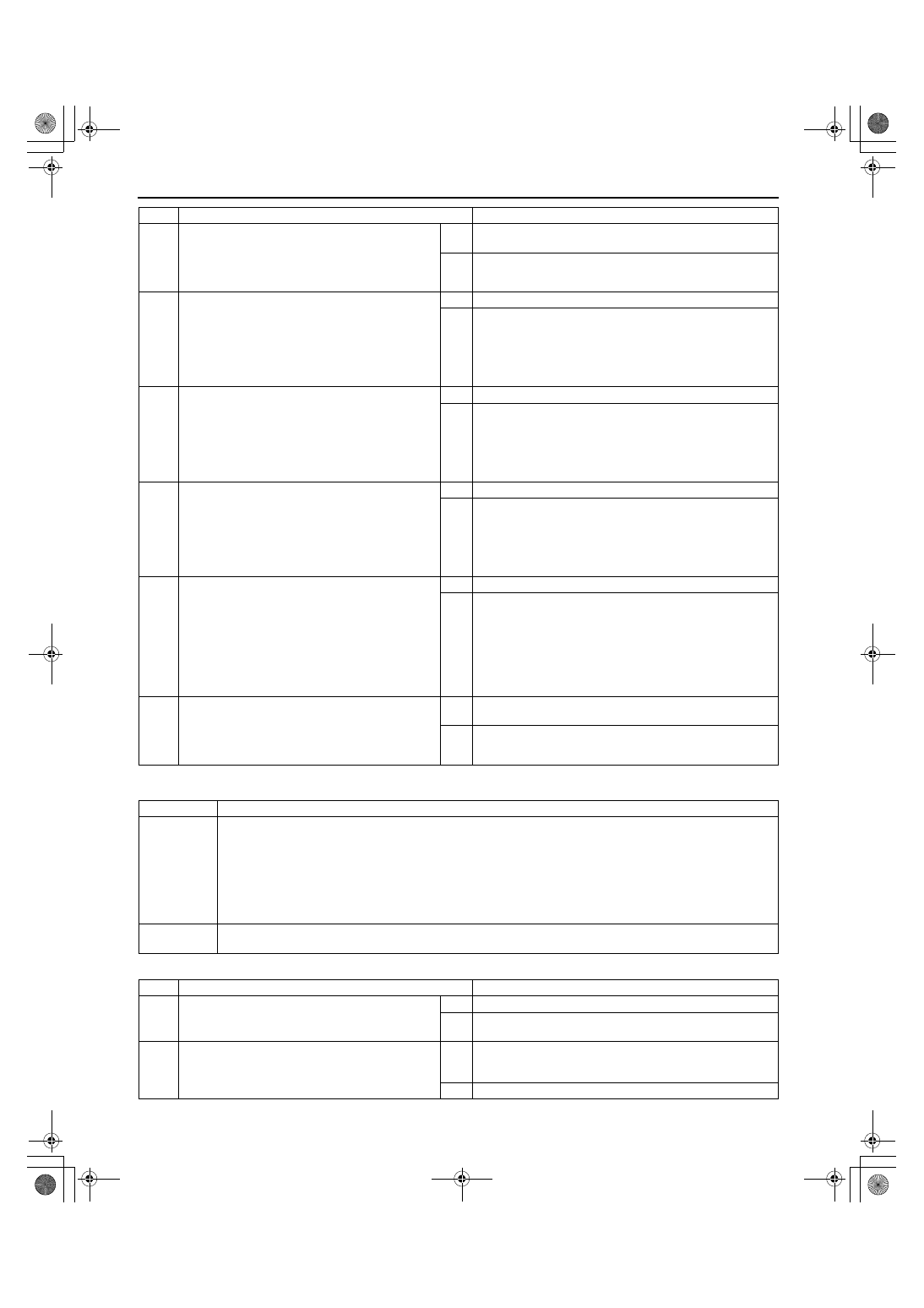
DTC P0464 [FS]
A3U010201086W14
Diagnostic procedure
4
INSPECT FUEL GAUGE SENDER UNIT
•
Inspect fuel gauge sender unit.
(See 09–22–13 FUEL GAUGE SENDER UNIT
INSPECTION.)
•
Is fuel gauge sender unit okay?
Yes Connect fuel gauge sender unit connector, then go to next
step.
No
Replace fuel gauge sender unit, then go to Step 8.
5
INSPECT FTL SIGNAL CIRCUIT FOR OPEN
CIRCUIT
•
Turn ignition key to ON (Engine OFF).
•
Measure voltage between fuel gauge sender
unit terminal A (harness-side) and body
ground.
•
Is voltage above 4.5—5.5 V?
Yes Go to Step 8.
No
Go to next step.
6
INSPECT PCM CONNECTOR FOR POOR
CONNECTION
•
Turn ignition key to OFF.
•
Disconnect PCM connector.
•
Check for poor connection (damaged/pulled-
out terminals, corrosion, etc.).
•
Is there malfunction?
Yes Repair suspected terminal, then go to Step 8.
No
Repair or replace open circuit between fuel gauge sender
unit terminal A (harness-side) and PCM terminal 63
(harness-side), then go to Step 8.
7
INSPECT FUEL GAUGE SENDER UNIT
GROUND CIRCUIT FOR OPEN CIRCUIT
•
Turn ignition key to OFF.
•
Check for continuity between fuel gauge
sender unit terminal C (harness-side) and body
ground.
•
Is there continuity?
Yes Go to next step.
No
Repair or replace harness for open, then go to next step.
8
VERIFY TROUBLESHOOTING OF DTC P0463
COMPLETED
•
Make sure to reconnect all disconnected
connectors.
•
Turn ignition key to ON (Engine OFF).
•
Clear DTC from memory using WDS or
equivalent.
•
Start engine.
•
Is pending code of same DTC present?
Yes Replace PCM, then go to next step.
No
No concern is detected.
Go to next step.
9
VERIFY AFTER REPAIR PROCEDURE
•
Perform “After Repair Procedure”.
(See 01–02B–9 AFTER REPAIR
PROCEDURE [FS].)
•
Is there any DTC present?
Yes Go to applicable DTC inspection.
(See 01–02B–15 DTC TABLE [FS].)
No
Troubleshooting completed.
STEP
INSPECTION
ACTION
DTC P0464
Fuel gauge sender unit circuit performance (slosh check)
DETECTION
CONDITION
•
PCM monitors fuel gauge sender unit input voltage at PCM terminal 63 while engine is running. If
differences are high for 14 seconds while vehicle is stopped, PCM determines that FTL signal is incorrect.
Diagnostic support note
•
This is a continuous monitor (CCM).
•
MIL illuminates if PCM detects the above malfunction condition in two consecutive drive cycles.
•
PENDING CODE is available if PCM detects the above malfunction condition during first drive cycle.
•
FREEZE FRAME DATA is available.
•
DTC is stored in PCM memory.
POSSIBLE
CAUSE
•
Fuel gauge sender unit malfunction or substandard performance
STEP
INSPECTION
ACTION
1
VERIFY FREEZE FRAME DATA HAS BEEN
RECORDED
•
Has FREEZE FRAME DATA been recorded?
Yes Go to next step.
No
Record FREEZE FRAME DATA on repair order, then go to
next step.
2
VERIFY RELATED REPAIR INFORMATION
AVAILABILITY
•
Check for related Service Bulletins availability.
•
Is any related repair information available?
Yes Perform repair or diagnosis according to available repair
information.
•
If vehicle is not repaired, Go to next step.
No
Go to next step.
1712-1U-01G(01-02B).fm 108 ページ 2001年6月29日 金曜日 午後3時24分