Mazda X-5. Manual - part 123
 

  Index      Mazda     Mazda X-5 - service repair manual 2006 year


Search            


Content   ..  121  122  123 


Mazda X-5. Manual - part 123


CONTROL SYSTEM 

09–40–5

09–40

On-Board Diagnostic Function

• The on-board diagnostic function is incorporated into the following module: 

— PCM

— TCM

— DSC HU/CM (with DSC)

— ABS HU/CM (with ABS)

— Keyless control module

— Steering angle sensor

— Instrument cluster

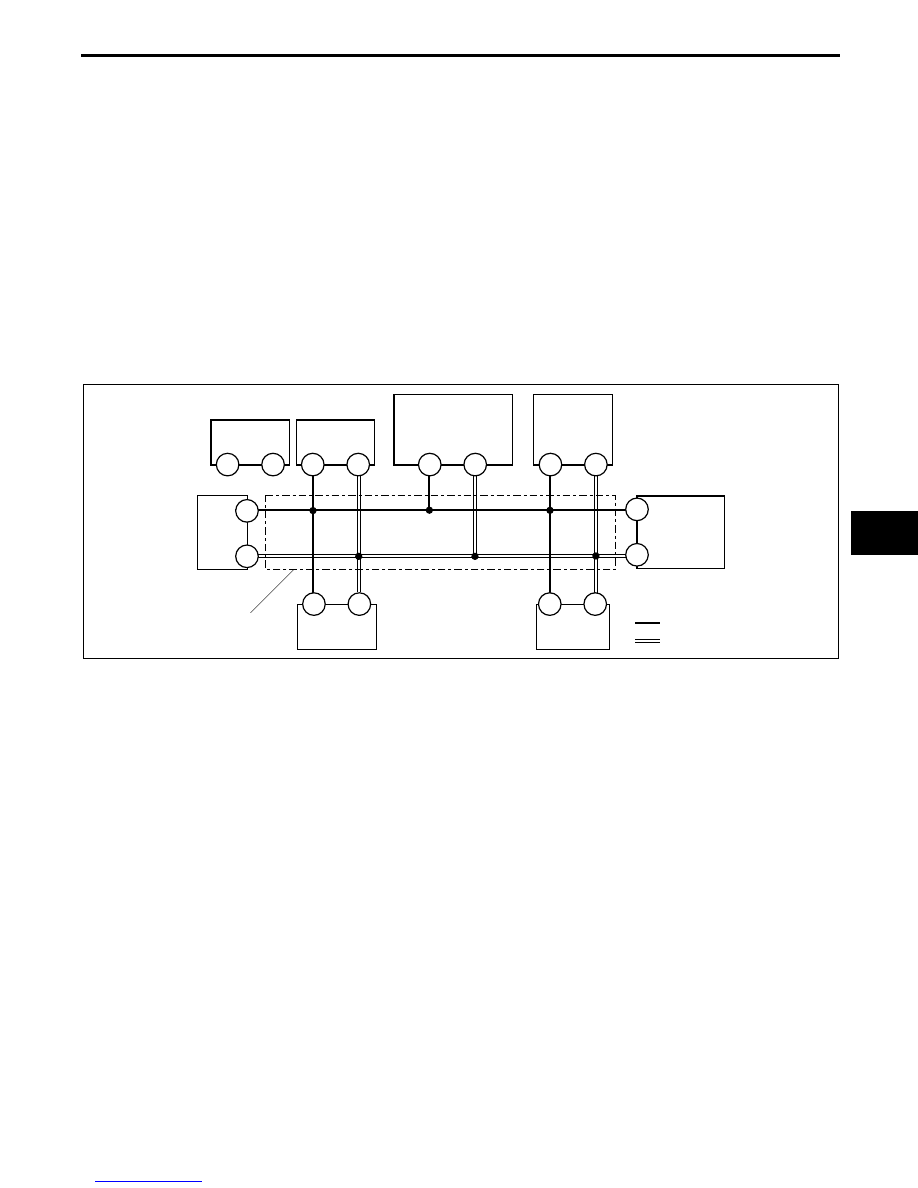
• This function can narrow down CAN system malfunction locations.

• The on-board diagnostic function consists of the following functions.

— Failure detection function, which detects DTCs malfunctions in CAN system-related parts.

— Memory function, which stores detected.

— Self-malfunction diagnostic function, which indicates system malfunctions using DTCs and warning lights.

• Using the WDS or equivalent, DTCs can be read out and deleted.

• The CAN system has a fail-safe function. When a malfunction occurs in CAN system, the transmission module 

sends a warning signal and the receiving module illuminates the warning light.

Block diagram

Failure detection function

• The failure detection function in each CAN system-related module detects malfunctions in input/output signals.

• This function outputs the DTC for the detected malfunction to the DLC-2, and also sends the detected result to 

the memory function and fail-safe function.

Fail-safe function

• When the failure detection function determines that there is a malfunction, the fail-safe function illuminates a 

warning light to inform the driver of the malfunction.

Memory function

• The memory function stores the DTC for the malfunction of input/output signals for related parts, as determined 

by the failure detection function.

Self-malfunction diagnostic function

• The self-malfunction diagnostic function determines that there is a malfunction, and outputs a signal, as a DTC, 

to the DLC-2. The DTC can be read out using the WDS or equivalent.

F

E

Z

Y

1J

1L

CAN_H

CAN_L

DLC-2

1AI

1AM

4AA

4Z

1G

1C

PCM

ABS HU/CM 
(WITH ABS)

KEYLESS 
CONTROL MODULE 
(WITH ADVANCED 
KEYLESS SYSTEM)

TCM (AT)

INSTRUMENT 
CLUSTER

TWISTED PAIR

X

W

DSC HU/CM 
(WITH DSC)

E

F

STEERING 
ANGLE 
SENSOR 
(WITH DSC)

E5U940ZS5002

CONTROL SYSTEM 

09–40–6

DTC table

Narrowing down malfunction locations

• The on-board diagnostic function, by verifying the detected DTC information from each module, can narrow 

down a CAN system malfunction location. Refer to the self-malfunction diagnostic function for detailed 
information regarding DTCs. (See09–40–5 Self-malfunction diagnostic function.)

Flowchart

DTC

Malfunction location

DTC output module

U0073

CAN system communication error

• PCM

• TCM

• ABS HU/CM

• DSC HU/CM

• Keyless control module

• Instrument cluster

U0100

Communication error to PCM

• TCM

• DSC HU/CM

• Keyless control module

• Instrument cluster

U0101

Communication error to TCM

• PCM

• DSC HU/CM

• Instrument cluster

U0121

Communication error to ABS HU/CM or DSC HU/CM

• PCM

• Instrument cluster

U0155

Communication error to instrument cluster

• PCM

• DSC HU/CM

U0214

Communication error to keyless control module

Instrument cluster

U0323

Communication error to instrument cluster

Keyless control module

U1900

Communication error to other module

• ABS HU/CM

• DSC HU/CM

• Steering angle sensor

U2023

Abnormal message from PCM

• ABS HU/CM

• DSC HU/CM

• Keyless control module

U2516

CAN system communication error

Steering angle sensor

START

Verify that DTCs are displayed for PCM, TCM, DSC HU/CM, ABS HU/CM, keyless control module, 
steering angle sensor, and instrument cluster.
Are any DTCs display?

Yes

No

END

Determine the malfunctioning part of the CAN system.

END

E5U940ZS5003

CONTROL SYSTEM 

09–40–7

09–40

Example (PCM-related communication error)

Note

• This example is for MT with DSC.

1. DTCs for the PCM, DSC HU/CM, steering angle sensor and instrument cluster can be verified using the WDS 

or equivalent.

2. If there is a communication error between the instrument cluster and PCM, even if the communication between 

the DSC HU/CM and the instrument cluster is normal, it is probable that there is a malfunction in the PCM or 
PCM-related wiring harnesses.

End Of Sie

Module

Displayed DTC

Probable malfunction location

PCM

U0073

PCM-related CAN system malfunction

U0121

Communication error between PCM and DSC HU/CM

U0155

Communication error between PCM and instrument cluster

DSC HU/CM

U0100

Communication error between DSC HU/CM and PCM

Instrument cluster

U0100

Communication error between instrument cluster and PCM

DLC-2

PCM

: TWISTED PAIR

INSTRUMENT CLUSTER

DSC HU/CM

NORMAL

COMMUNICATION 
ERROR

COMMUNICATION 
ERROR

E5U940ZS5004


Content   ..  121  122  123