Lifan 620. Manual - part 67


  Index      Lifan     Lifan 620 - service repair manual 2008 year


Search            


Content   ..  65  66  67  68   ..


Lifan 620. Manual - part 67


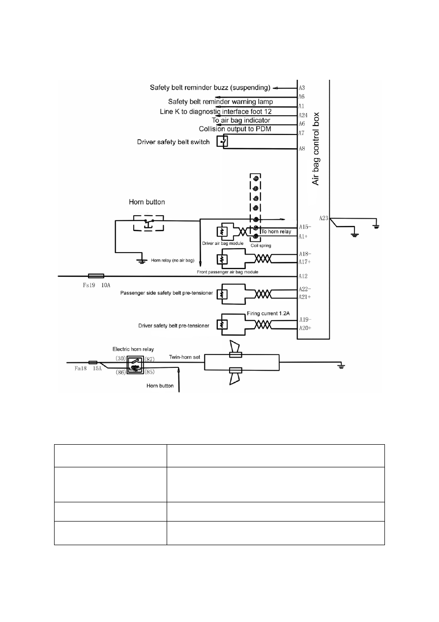
1. Check circuit as shown in Fig. 4-118 


Deficiency of the two horns 

1. Fuse blown                                    2. Deficiency of horn relay 

3. Deficiency of horn switch            4. Deficiency of horn 

5. Fault in clock spring           6. Fault in wiring 

Deficiency of one horn 

1. Deficiency of horn        2. Fault in wiring 

Horn keeps chirping   

1. Deficiency of horn relay        2. Deficiency of horn switch 

3. Fault in clock spring           4. Fault in wiring 


269

Chapter V  Air Bag


Section I


Composition, Principle and Safety Rules for Maintenance


I. Composition & layout of air bag system 


Fig. 5-1 


The air bag ECU can keep in operation for over 100ms under the circumstances that the battery 
voltage drops too low or the power supply disconnects because of collision. Two models of the air 
bag are involved in the LF7162: the two circuits and four circuits which must work simultaneously 
with the front pre-tensioned safety belt. 

270

2. Driver air bag module 
The un-removable driver air bag module, containing gas generator, bag, ornamental cap and a 
series of auxiliary components, is installed in the central ornamental cap of the steering wheel, as 
shown in Fig. 5-2. 

 
The working principle of air bag clock spring: The installation housing of the clock spring is fixed on 
the steering column, and the upper part of the clock spring turn plate is inserted into the steering 
wheel, and the swirly cable is installed between the turnplate and installation housing. When the 
steering wheel turns left or right, the clock spring turnplate will turn simultaneously with the 
steering wheel, turning the output end of the cable and stretching or tightening the swirly cable. 
For this reason, the harness is prevented from being wound upon the steering column. Beyond 
that, the continuity of the harness and the connection of the electronic signal are assured. Thus, 
the harness of the clock spring is also the bridge for supplying electricity from the vehicle body to 
the related functional components of steering wheel.   

271

4. Front passenger air bag module 
The front passenger air bag module, comprising of gas generator, bag and a series of auxiliary 
components, etc, is installed above the sundries box of dash board, as shown in Fig. 5-4. 


Fig. 5-5 


272


Content   ..  65  66  67  68   ..