Lexus LC500 (2022 year). Manual in english - page 14
 

  Index      Manuals     Lexus LC500 (2022 year). Manual in english


Search            copyright infringement  


Content      ..     12      13      14      15     ..


Lexus LC500 (2022 year). Manual in english - page 14


243

4

4-5. Using the driving support systems

Dr

ivin
g

O

The vehicle is approaching a tall or 

curved curb.

O

Driving close to columns (H-shaped steel 

beams, etc.) in multi-story parking 

garages, construction sites, etc.

O

If the vehicle cannot be driven in a stable 

manner, such as when the vehicle has 

been in an accident or is malfunctioning.

O

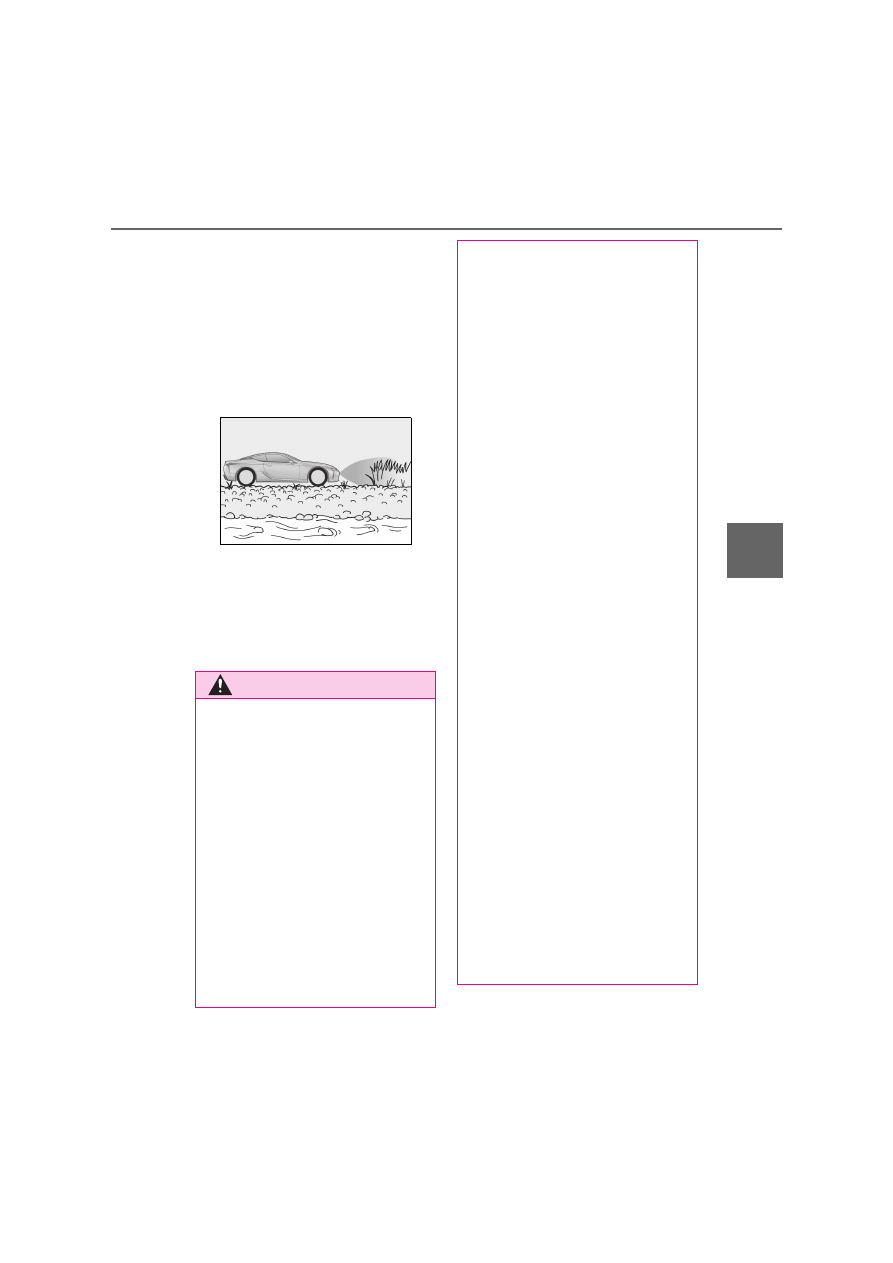
On an extremely bumpy road, on an 

incline, on gravel, or on grass.

O

When tire chains, a compact spare tire or 

an emergency tire puncture repair kit are 

used.

Q

Customization

Some functions can be customized. 

(

P.425)

WARNING

Q

Cautions regarding the use of the 

system

There is a limit to the degree of recogni-

tion accuracy and control performance 

that this system can provide, do not 

overly rely on this system. The driver is 

always responsible for paying attention 

to the vehicle’s surroundings and driving 

safely.

Q

To ensure the system can operate 

properly

Observe the following precautions. 
Failing to do so may result in the vehicle 

being unable to be driven safely and pos-

sibly cause an accident.

O

Do not damage the sensors, and 

always keep them clean.

O

Do not attach a sticker or install an 

electronic component, such as a 

backlit license plate (especially fluo-

rescent type), fog lights, fender pole or 

wireless antenna near a radar sensor.

O

Do not subject the surrounding area of 

the sensor to a strong impact. If sub-

jected to an impact, have the vehicle 

inspected by any authorized Lexus 

retailer or Lexus authorized repairer, 

or any reliable repairer. If the front or 

rear bumper needs to be 

removed/installed or replaced, con-

tact any authorized Lexus retailer or 

Lexus authorized repairer, or any reli-

able repairer.

O

Do not modify, disassemble or paint 

the sensors.

O

Do not attach a license plate cover.

O

Keep your tires properly inflated.

Q

When to disable the function

In the following situations, disable the 

function as it may operate even though 

there is no possibility of a collision.

O

Failing to observe the warnings above.

O

A non-genuine Lexus suspension 

(lowered suspension, etc.) is installed.

Q

Notes when washing the vehicle

O

Do not apply intensive bursts of water 

or steam to the sensor area. Doing so 

may result in the sensor malfunction-

ing.

O

When using a high pressure washer to 

wash the vehicle, do not spray the sen-

sors directly, as doing so may cause a 

sensor to malfunction.

O

When using steam to clean the vehi-

cle, do not direct steam too close to 

the sensors as doing so may cause a 

sensor to malfunction.

244

4-5. Using the driving support systems

Q

Detection range of the sensors

Approximately 100 cm (3.3 ft.)

Approximately 150 cm (4.9 ft.)

Approximately 60 cm (2.0 ft.)

The diagram shows the detection range of 
the sensors. Note that the sensors cannot 
detect obstacles that are extremely close 
to the vehicle.
The range of the sensors may change 
depending on the shape of the object etc.

Q

Multi-information display, head-up 
display and Center Display

Sensors that detect an obstacle will illu-
minate continuously or blink.

NOTICE

Q

When using Lexus parking assist-sen-

sor

In the following situations, the system 

may not function correctly due to a sen-

sor malfunction etc. Have the vehicle 

checked by any authorized Lexus 

retailer or Lexus authorized repairer, or 

any reliable repairer.

O

The Lexus parking assist-sensor oper-

ation display flashes or shows continu-

ously, and a beep sounds when no 

obstacles are detected.

O

If the bumper or grille collides with 

something.

O

If the display flashes or shows continu-

ously without beeping, except when 

the mute function has been turned on.

O

If a display error occurs, first check the 

sensor. 

If the error occurs even when there is 

no ice, snow or mud on the sensor, it is 

likely that the sensor is malfunctioning.

Sensor detection display, obsta-
cle distance

Display

*1

Approximate distance 

to obstacle

(continuous

*2

 or 

blinking 

slowly

*3

)

Front center sensor:
100 cm (3.3 ft.) to 50 
cm (1.6 ft.)
Rear center sensor:
150 cm (4.9 ft.) to 60 
cm (2.0 ft.)

(continuous

*2

or 

blinking

*3

)

Front center sensor:
50 cm (1.6 ft.) to 40 cm 
(1.3 ft.)
Rear center sensor:
60 cm (2.0 ft.) to 45 
cm (1.5 ft.)
Front and rear corner 
sensor:
60 cm (2.0 ft.) to 45 
cm (1.5 ft.)

A
B
C

245

4

4-5. Using the driving support systems

Dr

ivin
g

*1

: The illustrations show the graphics on 

the Multi-information display, and differ 
from the graphics on the head-up dis-
play and Center Display. Depending on 
the distance of the obstacle, the sensor 
display on Center Display illuminates or 
blinks in various cycles, although the 
width of it does not change.

*2

: Multi-information display and head-up 

display

*3

: Center  Display

Q

Buzzer operation and distance to 
an obstacle

A buzzer sounds when the sensors are 
operating.

The buzzer beeps faster as the vehi-
cle approaches an obstacle. When 

the vehicle comes within the follow-
ing distance of the obstacle, the 
buzzer sounds continuously:

• Front center sensors: Approximately 30 

cm (1.0 ft.)

• Corner sensors: Approximately 30 cm 

(1.0 ft.)

• Rear center sensors: Approximately 35 

cm (1.1 ft.)

When 2 or more obstacles are 
detected simultaneously, the buzzer 
system responds to the nearest 
obstacle. If one or both come within 
the above distances, the beep will 
repeat a long tone, followed by fast 
beeps.

(continuous

*2

 or 

blinking rap-

idly

*3

)

Front center sensor:
40 cm (1.3 ft.) to 30 cm 
(1.0 ft.)
Rear center sensor:
45 cm (1.5 ft.) to 35 cm 
(1.1 ft.)
Front and rear corner 
sensor:
45 cm (1.5 ft.) to 30 cm 
(1.0 ft.)

(blinking

*2

 or 

continuous

*3

)

Front center sensor:
Less than 30 cm (1.0 ft.)
Rear center sensor:
Less than 35 cm (1.1 ft.)
Front and rear corner 
sensor:
Less than 30 cm (1.0 ft.)

Display

*1

Approximate distance 

to obstacle

246

4-5. Using the driving support systems

*

: If equipped

Multi-information display

The BSM function/RCTA function can be 
turned on/off.
The RCTA function is available when the 
BSM function is on.

Outside rear view mirror indicators

BSM function: 
When a vehicle is detected in a blind spot 
of the outside rear view mirrors or 
approaching rapidly from behind into a 
blind spot, the outside rear view mirror 
indicator on the detected side will illumi-
nate. If the turn signal lever is operated 
toward the detected side, the outside rear 
view mirror indicator will flash.
RCTA function: 
When a vehicle approaching from the right 
or left at the rear of the vehicle is detected, 
both outside rear view mirror indicators 
will flash.

BSM indicator/RCTA indicator

When the BSM function/RCTA function is 
turned on, the indicator comes on.

Monitor screen display (RCTA 
function only)

If a vehicle approaching from the right or 
left at the rear of the vehicle is detected, 
the RCTA icon (

P.251) for the detected 

side will be displayed on the monitor 
screen. This illustration shows an example 
of a vehicle approaching from the left at 
the rear of the vehicle.

RCTA buzzer (RCTA function 
only)

If a vehicle approaching from the right or 
left at the rear of the vehicle is detected, a 
buzzer will sound. The buzzer also sounds 
for approximately 1 second immediately 
after the BSM function is operated to turn 
the system on.

BSM (Blind Spot Monitor)

*

The Blind Spot Monitor uses the 
sensors installed behind the rear 
bumper. The system is intended to 
assist the driver check areas that 
are not easily visible. The system 
has the following 2 functions:

The BSM (Blind Spot Monitor) 
function

Assists the driver in making a deci-
sion when changing lanes

The RCTA (Rear Crossing Traffic 
Alert) function

Assists the driver when backing up

These functions use same sensors.

System components

A

B

C

D

E

247

4

4-5. Using the driving support systems

Dr

ivin
g

1

Press 

 or 

 of the meter con-

trol switches, select 

.

2

Press 

 or 

 of the meter con-

trol switches, select “BSM”, and 
press “OK”.

3

Press 

 or 

 of the meter con-

trol switches, select “BSM” or 
“RCTA”, and press “OK”.

Q

Outside rear view mirror indicator visi-

bility

In strong sunlight, the outside rear view mir-

ror indicator may be difficult to see.

Q

Hearing the RCTA buzzer

The RCTA buzzer may be difficult to hear 

over loud noises, such as if the audio system 

volume is high.

Q

When “Blind Spot Monitor Unavailable” 

is shown on the multi-information dis-

play

Water, snow, mud, etc., may be built up in 

the vicinity of the sensor area of the 

bumper. (

P.247) Removing the water, 

snow, mud, etc., from the vicinity of the sen-

sor area of the bumper should return it to 

normal.
Also, the sensor may not function normally 

when used in extremely hot or cold 

weather.

Q

When “Blind Spot Monitor System Mal-

function Visit Your Dealer” is shown on 

the multi-information display

There may be a sensor malfunction or volt-

age abnormality. Have the vehicle 

inspected at any authorized Lexus retailer 

or Lexus authorized repairer, or any reli-

able repairer.

Q

Customization

Some functions can be customized.

(Customizable features: 

P.425)

Turning the BSM func-
tion/RCTA function on/off

WARNING

Q

To ensure the system can operate 

properly

Blind Spot Monitor sensors are installed 

behind the left and right sides of the rear 

bumper respectively. Observe the fol-

lowing to ensure the Blind Spot Monitor 

can function correctly.

O

Keep the sensors and the surrounding 

areas on the rear bumper clean at all 

times.

If a sensor or its surrounding area on 

the rear bumper is dirty or covered 

with snow, the Blind Spot Monitor may 

not operate and a warning message 

(

P.247) will be displayed. In this sit-

uation, clear off the dirt or snow and 

drive the vehicle with the operation 

conditions of the BSM function 

(

P.249) satisfied for approximately 

10 minutes. If the warning message 

does not disappear, have the vehicle 

inspected by any authorized Lexus 

retailer or Lexus authorized repairer, 

or any reliable repairer.

248

4-5. Using the driving support systems

Q

Operation of the BSM function

The BSM function uses radar sensors to detect the following vehicles traveling in 
adjacent lanes and advises the driver of the presence of such vehicles via the indi-
cators on the outside rear view mirrors.

Vehicles that are traveling in areas that are not visible using the outside rear 

WARNING

O

Do not subject a sensor or its sur-

rounding area on the rear bumper to a 

strong impact.

If a sensor is moved even slightly off 

position, the system may malfunction 

and vehicles may not be detected cor-

rectly.

In the following situations, have your 

vehicle inspected by any authorized 

Lexus retailer or Lexus authorized 

repairer, or any reliable repairer.

• A sensor or its surrounding area is 

subject to a strong impact.

• If the surrounding area of a sensor is 

scratched or dented, or part of them 

has become disconnected.

O

Do not disassemble the sensor.

O

Do not attach stickers to the sensor or 

surrounding area on the rear bumper.

O

Do not modify the sensor or surround-

ing area on the rear bumper.

O

Do not paint the rear bumper any 

color other than an official Lexus color.

BSM function

A

249

4

4-5. Using the driving support systems

Dr

ivin
g

view mirrors (the blind spots)

Vehicles that are approaching rapidly from behind in areas that are not visible 
using the outside rear view mirrors (the blind spots)

Q

BSM function detection areas

The areas that vehicles can be detected in are outlined below.

The range of each detection area is:

Approximately 0.5 m (1.6 ft.) to 3.5 m (11.5 ft.) from either side of the vehicle

*1

Approximately 1 m (3.3 ft.) forward of the rear bumper

Approximately 3 m (9.8 ft.) from the rear bumper

Approximately 3 m (9.8 ft.) to 60 m (197 ft.) from the rear bumper

*2

*1

: The area between the side of the vehicle and 0.5 m (1.6 ft.) from the side of the vehicle 

cannot be detected.

*2

: The greater the difference in speed between your vehicle and the detected vehicle is, 

the farther away the vehicle will be detected, causing the outside rear view mirror indi-
cator to illuminate or flash.

Q

The BSM function is operational when

The BSM function is operational when all of 

the following conditions are met:

O

The BSM function is on.

O

The shift position is in a position other 

than R.

O

The vehicle speed is greater than 

approximately 16 km/h (10 mph).

Q

The BSM function will detect a vehicle 

when

The BSM function will detect a vehicle pres-

ent in the detection area in the following sit-

uations:

O

A vehicle in an adjacent lane overtakes 

your vehicle.

O

You overtake a vehicle in adjacent lane 

slowly.

O

Another vehicle enters the detection 

area when it changes lanes.

Q

Conditions under which the system will 

not detect a vehicle

The BSM function is not designed to detect 

the following types of vehicles and/or 

objects:

O

Small motorcycles, bicycles, pedestrians, 
etc.

*

O

Vehicles traveling in the opposite direc-

B

A
B
C
D

250

4-5. Using the driving support systems

tion

O

Guardrails, walls, signs, parked vehicles 
and similar stationary objects

*

O

Following vehicles that are in the same 
lane

*

O

Vehicles traveling 2 lanes away from 
your vehicle

*

O

Vehicles which are being overtaken rap-
idly by your vehicle.

*

*

: Depending on the conditions, detection 

of a vehicle and/or object may occur.

Q

Conditions under which the system may 

not function correctly

O

The BSM function may not detect vehi-

cles correctly in the following situations:

• When the sensor is misaligned due to a 

strong impact to the sensor or its sur-

rounding area

• When mud, snow, ice, a sticker, etc. is 

covering the sensor or surrounding area 

on the rear bumper

• When driving on a road surface that is 

wet with standing water during bad 

weather, such as heavy rain, snow, or fog

• When multiple vehicles are approaching 

with only a small gap between each vehi-

cle

• When the distance between your vehicle 

and a following vehicle is short

• When there is a significant difference in 

speed between your vehicle and the 

vehicle that enters the detection area

• When the difference in speed between 

your vehicle and another vehicle is 

changing

• When a vehicle enters a detection area 

traveling at about the same speed as your 

vehicle

• As your vehicle starts from a stop, a vehi-

cle remains in the detection area

• When driving up and down consecutive 

steep inclines, such as hills, dips in the 

road, etc.

• When driving on roads with sharp bends, 

consecutive curves, or uneven surfaces

• When vehicle lanes are wide, or when 

driving on the edge of a lane, and the 

vehicle in an adjacent lane is far away 

from your vehicle

• When an accessory (such as a bicycle 

carrier) or towing eyelet is installed to the 

rear of the vehicle

• When there is a significant difference in 

height between your vehicle and the 

vehicle that enters the detection area

• Immediately after the BSM function is 

turned on

O

Instances of the BSM function unneces-

sarily detecting a vehicle and/or object 

may increase in the following situations:

• When the sensor is misaligned due to a 

strong impact to the sensor or its sur-

rounding area

• When the distance between your vehicle 

and a guardrail, wall, etc. that enters the 

detection area is short

• When driving up and down consecutive 

steep inclines, such as hills, dips in the 

road, etc.

• When vehicle lanes are narrow, or when 

driving on the edge of a lane, and a vehi-

cle traveling in a lane other than the adja-

cent lanes enters the detection area

• When driving on roads with sharp bends, 

consecutive curves, or uneven surfaces

• When the tires are slipping or spinning

• When the distance between your vehicle 

and a following vehicle is short

• When an accessory (such as a bicycle 

carrier) or towing eyelet is installed to the 

rear of the vehicle

251

4

4-5. Using the driving support systems

Dr

ivin
g

Q

Operation of the RCTA function

The RCTA function uses radar sensors to detect vehicles approaching from the 
right or left at the rear of the vehicle and alerts the driver of the presence of such 
vehicles by flashing the outside rear view mirror indicators and sounding a buzzer.

Approaching vehicles

Detection areas of approaching vehicles

Q

RCTA icon display

When a vehicle approaching from the 
right or left at the rear of the vehicle is 

detected, the following will be dis-
played on the monitor screen

WARNING

Q

Cautions regarding the use of the 

function

The driver is solely responsible for safe 

driving. Always drive safely, taking care 

to observe your surroundings.
The BSM function is a supplementary 

function which alerts the driver that a 

vehicle is in a blind spot of the outside 

rear view mirrors or is approaching rap-

idly from behind into a blind spot. Do not 

overly rely on the BSM function. As the 

function cannot judge if it is safe to 

change lanes, over reliance could lead to 

an accident resulting in death or serious 

injury.
As the system may not function correctly 

under certain conditions, the driver’s 

own visual confirmation of safety is nec-

essary.

RCTA function

A
B

252

4-5. Using the driving support systems

Q

RCTA function detection areas

The areas that vehicles can be detected in are outlined below.

The buzzer can alert the driver of faster 
vehicles approaching from farther away.

Example:

Q

The RCTA function is operational when

The RCTA function operates when all of the 

following conditions are met:

O

The RCTA function is on.

O

The shift position is in R.

O

The vehicle speed is less than approxi-

mately 8 km/h (5 mph).

O

The approaching vehicle speed is 

between approximately 8 km/h (5 mph) 

and 28 km/h (18 mph).

Display

Content

A vehicle is 
approaching from 
the left at the rear of 
the vehicle

A vehicle is 
approaching from 
the right at the rear 
of the vehicle

Vehicles are 
approaching from 
both sides of the 
vehicle

The RCTA function 
is malfunctioning 
(

P.247)

Display

Content

Approaching vehi-

cle speed

Approximate 

alert distance

28 km/h (18 mph) 

(fast)

20 m (65 ft.)

8 km/h (5 mph) 

(slow)

5.5 m (18 ft.)

A

253

4

4-5. Using the driving support systems

Dr

ivin
g

Q

Conditions under which the system will 

not detect a vehicle

The RCTA function is not designed to 

detect the following types of vehicles 

and/or objects:

O

Vehicles approaching from directly 

behind

O

Vehicles backing up in a parking space 

next to your vehicle

O

Vehicles that the sensors cannot detect 

due to obstructions

O

Guardrails, walls, signs, parked vehicles 
and similar stationary objects

*

O

Small motorcycles, bicycles, pedestrians, 
etc.

*

O

Vehicles moving away from your vehicle

O

Vehicles approaching from the parking 
spaces next to your vehicle

*

O

The distance between the sensor and 

approaching vehicle gets too close

*

: Depending on the conditions, detection 

of a vehicle and/or object may occur.

Q

Situations in which the system may not 

operate properly

The RCTA function may not detect vehicles 

correctly in the following situations:

O

When the sensor is misaligned due to a 

strong impact to the sensor or its sur-

rounding area.

O

When mud, snow, ice, a sticker, etc., is 

covering the sensor or surrounding area 

on the rear bumper.

O

When driving on a road surface that is 

wet with standing water during bad 

weather, such as heavy rain, snow, or fog.

O

When multiple vehicles are approaching 

with only a small gap between each vehi-

cle.

O

When a vehicle is approaching at high 

speed.

O

When equipment that may obstruct a 

sensor is installed, such as a towing eye-

let, bumper protector (an additional trim 

strip, etc.), bicycle carrier, or snow plow.

O

When backing up on a slope with a sharp 

change in grade.

O

When backing out of a sharp angle park-

ing spot.

O

When towing a trailer.

O

When there is a significant difference in 

height between your vehicle and the 

vehicle that enters the detection area.

O

When a sensor or the area around a sen-

sor is extremely hot or cold.

O

If the suspension has been modified or 

tires of a size other than specified are 

installed.

O

If the front of the vehicle is raised or low-

ered due to the carried load.

254

4-5. Using the driving support systems

O

When turning while backing up.

O

When a vehicle turns into the detection 

area.

Q

Situations in which the system may 

operate even if there is no possibility of a 

collision

Instances of the RCTA function unneces-

sarily detecting a vehicle and/or object may 

increase in the following situations:

O

When the parking space faces a street 

and vehicles are being driven on the 

street.

O

When the distance between your vehicle 

and metal objects, such as a guardrail, 

wall, sign, or parked vehicle, which may 

reflect electrical waves toward the rear of 

the vehicle, is short.

O

When equipment that may obstruct a 

sensor is installed, such as a towing eye-

let, bumper protector (an additional trim 

strip, etc.), bicycle carrier, or snow plow.

O

When a vehicle passes by the side of your 

vehicle.

O

When a detected vehicle turns while 

approaching the vehicle.

O

When there are spinning objects near 

your vehicle such as the fan of an air con-

ditioning unit.

O

When water is splashed or sprayed 

toward the rear bumper, such as from a 

sprinkler.

O

Moving objects (flags, exhaust fumes, 

large rain droplets or snowflakes, rain 

water on the road surface, etc.).

O

When the distance between your vehicle 

and a guardrail, wall, etc., that enters the 

detection area is short.

O

Gratings and gutters.

O

When a sensor or the area around a sen-

255

4

4-5. Using the driving support systems

Dr

ivin
g

sor is extremely hot or cold.

O

If the suspension has been modified or 

tires of a size other than specified are 

installed.

O

If the front of the vehicle is raised or low-

ered due to the carried load.

*

: If  equipped

Multi-information display (

P.96)

Displays the status of the active rear wing

Active rear wing switch

Operates the active rear wing manually

Indicator

Illuminates when the active rear wing is 
raised and turns off when it is retracted

WARNING

Q

Cautions regarding the use of the 

function

There is a limit to the degree of recogni-

tion accuracy and control performance 

that this system can provide, do not 

overly rely on this system. The driver is 

always responsible for paying attention 

to the vehicle’s surroundings and driving 

safely. (

P.251)

Q

To ensure the system can operate 

properly

P.247

Active rear wing

*

The vehicle is equipped with an 
active rear wing that operates 
automatically while the vehicle is 
being driven. This active rear wing 
enhances aerodynamic perfor-
mance, especially at high speeds, 
contributing to a more stable ride.
The active rear wing can be con-
trolled manually using a switch.

System components

A

B

C

256

4-5. Using the driving support systems

Q

The active rear wing can be operated 

when

O

The engine switch <power switch> is in 

IGNITION ON mode <ON mode>.

O

The trunk is closed.

O

The active rear wing has been activated 

in a customized setting.

Q

Conditions which stop the operation

In the following situations operation of the 

active rear wing will stop:

O

The engine switch <power switch> is 

turned to ACCESSORY mode or off 

while the active rear wing is operating.

O

The trunk is opened while the active rear 

wing is operating.

O

The raising operation of the active rear 

wing is interrupted by an object, etc.

O

The active rear wing is operated in an 

unusual manner causing it to stop at an 

irregular position.

In such cases, pressing the active rear wing 

switch will fully raise the active rear wing. 

Or, begin driving the vehicle and the active 

rear wing will raise automatically when the 

vehicle speed reaches 25 km/h (16 mph).

Q

When there is a malfunction in the sys-

tem

A warning message will be displayed on the 

multi-information display. (

P.381)

Q

Customization

The active rear wing can be turned on/ off. 

(Customizable features: 

P.425)

The active rear wing will operate auto-
matically at the following speeds 
according to the selected driving 
mode (

P.238).

(Always observe the legal speed limit 
when driving on public roads.)

When other than Eco drive mode is 
selected
Up: Approximately 80 km/h (50 
mph)
Down: Approximately 40 km/h (25 
mph)

When Eco drive mode is selected
Up: Approximately 130 km/h (80 
mph)
Down: Approximately 40 km/h (25 
mph)

Operate the active rear wing switch to 
raise/retract the active rear wing man-
ually.
The active rear wing retracts when it is 
raised and raises when retracted.
However, the active rear wing does 
not respond to switch operations while 

NOTICE

Q

To prevent system damage

O

Do not apply pressure to the active 

rear wing when pushing or pulling the 

vehicle.

O

Do not lean on the active rear wing.

O

Do not attach any accessories or other 

objects to the active rear wing.

O

Do not modify or disassemble the 

active rear wing.

O

Do not subject the active rear wing to 

severe impact.

Q

To prevent 12-volt battery discharge

Do not operate the active rear wing 

repeatedly while the engine <hybrid sys-

tem> is turned off.

Automatic operation

Changing to manual operation

257

4

4-5. Using the driving support systems

Dr

ivin
g

the active rear wing is operating.

*

: Press and hold the switch until the indi-

cator turns off. If the switch is released 
while the active rear wing is moving, it 
will return to the raised position auto-
matically.

Q

Restoring automatic operation after the 

active rear wing is operated manually

If the active rear wing is operated manually, 

automatic operation will resume according 

to the vehicle speed.

Vehicle speed

Up/Down

0 km/h (0 mph) 

(vehicle stopped)

Press/Press and 

hold

*

Approximately 0 – 

20 km/h (0 – 12 

mph)

Operation not pos-

sible

Approximately 20 – 

120 km/h (12 – 75 

mph)

Press/Press

Approximately 120 

km/h (75 mph) or 

more

Operation not pos-

sible

WARNING

Q

When manually operating the active 

rear wing

Observe the following precautions 

before operating the active rear wing. 

Failure to do so may result in death or 

serious injury.

O

Ensure that the surrounding area is 

free of any objects that may come into 

contact with or get caught on the 

active rear wing.

O

If there are people near the active rear 

wing, make sure that there is no possi-

bility of their clothing, personal 

belongings or body parts getting 

caught. Children especially should be 

warned not to touch the active rear 

wing while it is being operated.

O

If there is a risk that an object may 

become caught on the active rear 

wing during operation, stop operation 

immediately.

258

4-5. Using the driving support systems

*

: If equipped

Q

Fixed rear wing

The rear wing uses CFRP (Carbon Fiber 

Reinforced Plastic) parts, therefore pay 

attention to the following:

O

As the CFRP parts may change color if 

they are exposed to ultraviolet rays for 

extended periods of time, Lexus recom-

mends that your vehicle be stored in a 

place where it will not be exposed to 

direct sunlight.

O

Do not use wax that contains abrasives.

O

Do not use automatic car washes as they 

may scratch the CFRP parts and damage 

the paint, or may damage the rear wing.

To close the trunk, press the portions 

 of the rear wing.

Fixed rear wing

*

Installing a fixed rear wing will 
increase aerodynamic perfor-
mance when driving and will help to 
improve both driving stability and 
riding comfort.

WARNING

Q

When opening and closing the trunk

Observe the following precautions. Fail-

ure to do so may cause injury or serious 

damage.

O

Be careful that you do not bump the 

edge of the rear wing with your hands, 

arms, face or other parts of your body.

O

Do not leave your hand between the 

rear wing and trunk lid while opening 

the trunk. Your hand, arm or other part 

of your body may get caught when 

opening the trunk.

O

Do not sit on or lean against the rear 

wing, or place an excessive load on it. 

Failure to do so may damage the rear 

wing.

O

Do not attach any accessories other 

than genuine Lexus parts to the trunk 

lid. Such additional weight on the trunk 

lid may cause the lid to suddenly shut 

again after it is opened, dropping 

down on your head or body.

Q

Disassembly and modification

Do not disassemble or modify the rear 

wing as doing so may reduce driving sta-

bility.

NOTICE

Q

To prevent damage to the rear wing

Observe the following precautions. Fail-

ure to do so may damage the rear wing.

O

Do not place heavy objects on the rear 

wing, sit on or lean against it, or place 

an excessive load on it.

O

Do not strike the edge of the rear wing 

with solid objects or subject it to strong 

impact.

O

Do not hold the edge of the rear wing 

while opening or closing the trunk.

Q

Disassembly and modification

Do not disassemble or modify the rear 

wing as doing so may cause water to 

enter the trunk.

When closing the trunk

A


Content      ..     12      13      14      15     ..