Lexus RX300 (MCU15). Manual - part 338
 

  Index      Lexus     Lexus RX300 series MCU15 - service repair manual


Search            


Content   ..  336  337  338  339   ..


Lexus RX300 (MCU15). Manual - part 338


I19261

Body ECU

Wireless Door Lock Tuner

2

RDA

B6

3

B6

16

17

PRG

IA2

IA2

17

18

LG

LG

L

L

RDA

W5

W5

PRG

DI–584

DIAGNOSTICS

BODY CONTROL SYSTEM

LEXUS RX300   (RM785E)

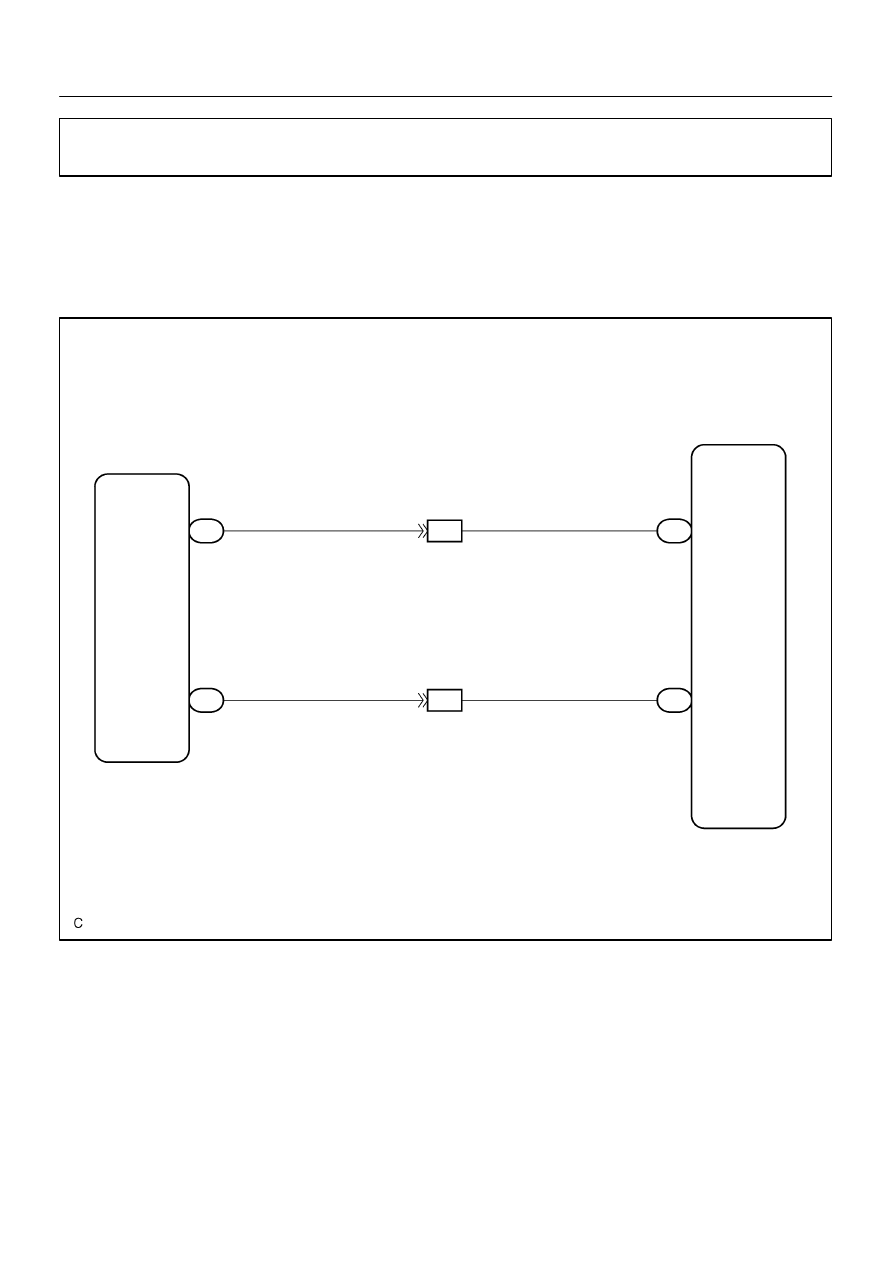
Wireless door lock tuner circuit

CIRCUIT DESCRIPTION

The signal from the transmitter will be input to the body ECU through RDA line. RDA line is diagnosed by
the Body ECU, so check DTC also in case of the failure of the wireless function.

WIRING DIAGRAM

DI1OP–06

DIAGNOSTICS

BODY CONTROL SYSTEM

DI–585

LEXUS RX300   (RM785E)

INSPECTION PROCEDURE

1

Check that DTC 42 is not output.

NG

Check the RDA line.

OK

2

Check wireharness.

PREPARATION:
Disconnect connectors of wireless door lock tuner and Body ECU.
CHECK:
Check continuity between terminals RCO of wireless door lock tuner and RCO of Body ECU.
OK:
Continuity

NG

Repair or replace wireharness.

OK

3

Check the wireless door lock tuner.

CHECK:
Replace the wireless door lock tuner and check if it recovers normally.
OK:
Must be recovered normally.

NG

Proceed to next circuit inspection shown on
problem symptoms table (See page DI–570).

OK

Failure of the original wireless door lock tun-
er.

I19262

Buckle 
SW

W–B

BE1

G–W

IA2

14

G–W

9

1

A

BF1

13

W–B (*2)

A

Body ECU

7

B7 DBKL

B12

A

(*1)

IM2

12

(*2)

G–W

BF1

8

(*1)

(*2)

(*2)

(*1)

1 B13

(*1)

4 B12

(*2)

4 B13

J17

J/C

16

BJ

BE1

J18

(*2)

(*1)

A

A

J17

J18

(*1)

(*2)

W–B

W–B (*1)

W–B (*1)

(*1)

W–B (*2)

J15
J/C

BM

(*2)

*1: LHD
*2: RHD

DI–586

DIAGNOSTICS

BODY CONTROL SYSTEM

LEXUS RX300   (RM785E)

Driver buckle switch circuit

WIRING DIAGRAM

DI1OT–05

DIAGNOSTICS

BODY CONTROL SYSTEM

DI–587

LEXUS RX300   (RM785E)

INSPECTION PROCEDURE

HINT:
In case of using the hand–held tester, start the inspection from step 1 and in case of not using the hand–held
tester, start from step 2.

1

Check driver buckle switch using hand–held tester.

PREPARATION:
Connect the hand–held tester to the DLC 3.
CHECK:
Check the driver buckle switch using DATA LIST.

OK

Proceed to next circuit inspection shown on
problem symptoms table (See page DI–570).

NG

2

Check driver buckle switch (See page BE–68).

NG

Replace the driver buckle switch.

OK

3

Check wireharness and connector between driver buckle switch and body
ground.

NG

Repair or replace wireharness or connector.

OK

Proceed to next circuit inspection shown on
problem symptoms table
(See page DI–570).


Content   ..  336  337  338  339   ..