Lexus RX300 (MCU15). Manual - part 80
V08425
LOCK
KNK
E6 Connector
(a) Remove the glove compartment (See page FI–68).
(b) Disconnect the E6 connector of ECM.
INSPECTION PROCEDURE
Replace knock sensor.
1
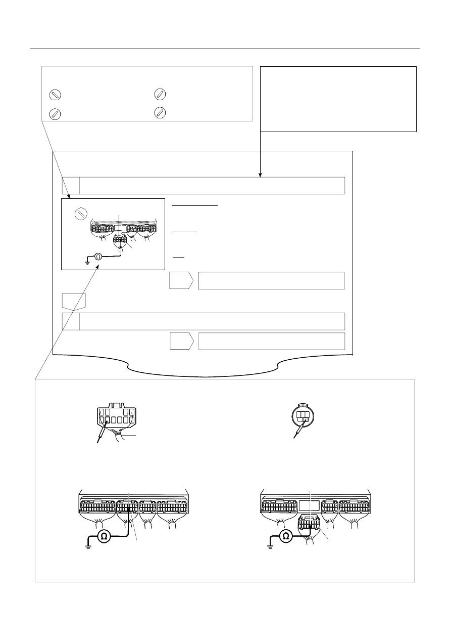
Check continuity between terminal KNK of ECM connector and body ground.
OK:
Check knock sensor (See page FI–61).
Measure resistance between terminal KNK of ECM connector
and body ground.
Resistance: 1 MΩ or higher
Connector being checked is connected.
D Indicates the condition of the connector of ECU during the check.
PREPARATION:
CHECK:
2
Go to step 3.
OK
OK
NG
D Indicates the position of the ignition switch during the check.
Check from the connector back side.
(with harness)
Ignition Switch LOCK (OFF)
Ignition Switch START
LOCK
Ignition Switch ON
Ignition Switch ACC
START
ON
ACC
D
D Indicates the place to check the voltage or resistance.
D Indicates the connector position to checked, from the front or back side.
Connector being checked is disconnected.
Check from the connector front side. (without harness)
In this case, care must be taken not to bend the terminals.
E6 Connector
KNK
Wire Harness
E6 Connector
KNK
A00255
AB0117
A00265
Inspection Procedure
Use the inspection procedure to determine if
the circuit is normal or abnormal, and, if it is
abnormal, use it to determine whether the
problem is located in the sensors, actuators,
wire harness or ECU.
–
INTRODUCTION
HOW TO TROUBLESHOOT ECU CONTROLLED
SYSTEMS
IN–31
LEXUS RX300 (RM785E)