Lexus SC300 / Lexus SC400. Manual - part 943
 

  Index      Lexus     Lexus SC300 / Lexus SC400 - service repair manual


Search            


Content   ..  941  942  943  944   ..


Lexus SC300 / Lexus SC400. Manual - part 943


TROUBLE SHOOTING:

Use the matrix chart below as a guide to repairs.  Verify necessary inputs to the A/C Control Assembly from
the vehicle prior to disassembly.  Use the repair manual, A/C system section, to validate such as B+, ILL+,
ground, etc..

SUSPECT AREA

SYMPTOM

Control

Switch

Indicator

Panel

Control

Lamp Circuit

Night Illumination does not

come on

LCD back lighting does not

come on

Indicator lamps of all

switches are off

Indicator lamp of all

switches are on

LCD is faulty

NOTE:

If symptoms still exist after the suspect areas have been tested and found not to be 
faulty, replace the amplifier.

1

LCD illumination bulbs are not serviceable, Control Switch must be replaced if illumination 
does not occur.

AIR CONDITIONING CONTROL DISASSEMBLY:

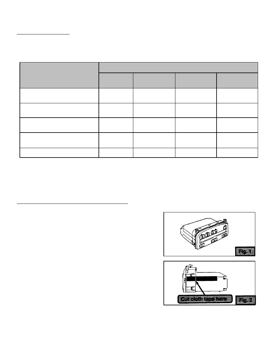
1. Remove Air Conditioning Control Assembly.

2. Separate Control Panel from case.

a. Cut the cloth tape on both sides of the case 

(See Fig. 2).

1992 - 1995 SC 300/400 A/C CONTROL ASSEMBLY SERVICE PARTS

Page 2 of 6

Bulb Switch


D


D

1


D


D


D


D

1992 - 1995 SC 300/400 A/C CONTROL ASSEMBLY SERVICE PARTS

Page 3 of 6

AIR CONDITIONING CONTROL DISASSEMBLY (Cont’d):

b. Remove 2 screws and release the 6 clips to 

separate the Control Panel from the case.

c. Disconnect 2 connectors to separate the 

Control Panel from the case.

d. Remove the wire harness (See Fig. 5).

3. Remove Control Switch.

a. To replace the Control Switch remove 2 

screws and release 4 clips (See Fig. 6).

b. Separate Control Switch from face plate.

4. Replace the Night Illumination Bulb.

Using a flat–bladed screwdriver, remove and 
replace the Night Illumination Bulb.

1992 - 1995 SC 300/400 A/C CONTROL ASSEMBLY SERVICE PARTS

Page 4 of 6

INSPECTION PROCEDURE:

1. Bulb Circuit:

D

Bulb Inspection – Perform the following test 
on suspect Night Illumination Bulbs.  Check 
for continuity as shown.  Replace the bulb if 
there is no continuity.

D

Bulb Circuit Inspection – Verify continuity 
between terminals 22 and 24.  If there is 
no continuity, replace Control Switch.

2. Switch Circuit:

D

Switch Continuity Inspection – Check that there 
is continuity between the terminals while the 
switch is pressed.

D

If there is no continuity between even one pair 
of terminals, replace the Control Switch.

SWITCH

A/C

MODE/R>

MODE/L<

REAR - DEF

FRONT - DEF

FRESH

RECIRC

OFF

FAN - DOWN

FAN - UP

13 - 17

13 - 16

13 - 15

12 - 17

12 - 16

12 - 15

12 - 14

11 - 17

11 - 16

11 - 15

INSPECTION

TERMINALS

1992 - 1995 SC 300/400 A/C CONTROL ASSEMBLY SERVICE PARTS

Page 5 of 6

INSPECTION PROCEDURE (Cont’d):

3. Indicator Lamp Circuit:

D

Connect two 1.5 v dry cell 
batteries in series.  Using the 
table, check that each suspect 
indicator lamp illuminates.

NOTE:

Since the indicator lamps 
are LEDs, do not mix the “+” 
and “–” terminals of the test 
batteries or apply power to 
them for more than 3 seconds 
at a time.

D

If a suspect LED does not illuminate 
when tested, replace the Control Switch.

INDICATOR

A/C

REAR - DEF

FRONT - DEF

FRESH

RECIRC

TERMINAL TO

CONNECT  “+”

10

20

20

19

19

TERMINAL TO
CONNECT  “-”

18

18

8

18

8


Content   ..  941  942  943  944   ..