Lexus SC300 / Lexus SC400. Manual - part 848


  Index      Lexus     Lexus SC300 / Lexus SC400 - service repair manual


Search            


Content   ..  846  847  848  849   ..


Lexus SC300 / Lexus SC400. Manual - part 848


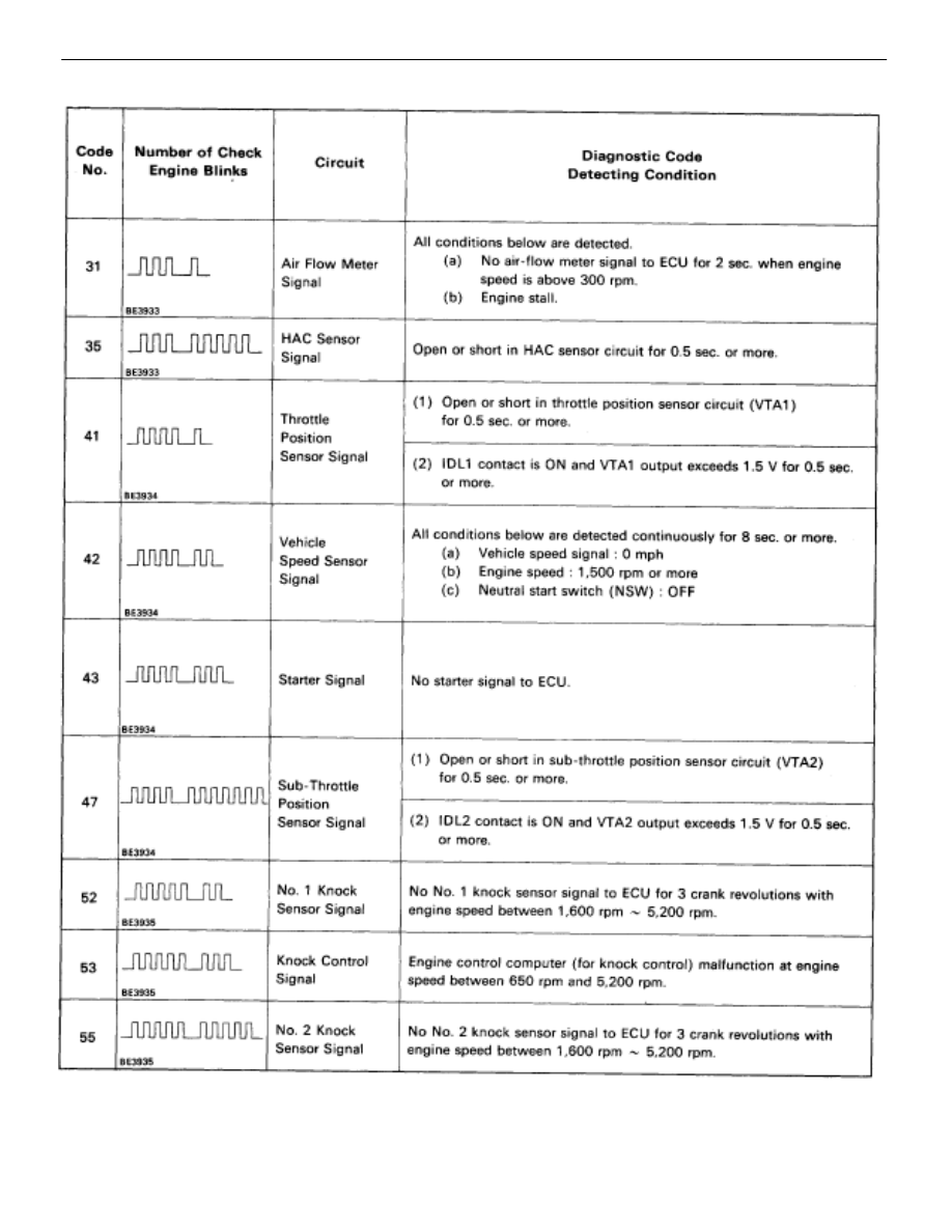
DIAGNOSTIC CODE CHART (Cont’d)

TR–18

ENGINE TROUBLESHOOTING

Diagnostic Code Chart
Trouble Area

”CHECK” 

Engine Warning

Light *


Memory*


See Page

Trouble Area

Normal

Mode

Test

Mode

Memory

See Page

Open or short in air flow meter circuit.

Air flow meter

ECU

ON

N.A.


TR–88

ECU

ON

ON


TR–92

Open or short in throttle position sensor circuit.

Throttle position sensor

ON

ON


TR–94

Throttle  osition sensor

 ECU

No. 1 speed sensor

Combination meter

Open or short in No. 1 speed sensor circuit.

ECU

ON

ON


TR–98

Open or short in starter signal circuit.

Open or short in ignition switch or main relay circuit.

ECU

N.A.

OFF

X

TR–100

Open or short in sub–throttle position sensor circuit.

Sub–throttle position sensor

OFF

ON


TR–94

Sub throttle  osition sensor

ECU

Open or short in No. 1 knock sensor circuit.

O en or short in No. 1 knock sensor circuit.

No. 1 knock sensor (looseness)

ON

N.A.


No. 1 knock sensor (looseness)

ECU


 ECU

ON

N.A.

X

TR–102

 Open or short in No. 2 knock sensor circuit.

 O en or short in No. 2 knock sensor circuit.

 No. 2 knock sensor (looseness)

ON

N.A.


 No. 2 knock sensor (looseness)

 ECU


*1, 2: See page 

TR–20

.

ENGINE TROUBLESHOOTING

Diagnostic Code Chart

TR–19

DIAGNOSTIC CODE CHART (Cont’d)

*1: ”ON” displayed in the diagnosis mode column indicates that the ”CHECK” Engine Warning Light is

lighted up when a malfunction is detected. ”OFF” indicates that the ”CHECK” does not light up during
malfunction diagnosis, even if a malfunction is detected. ”N.A.” indicates that the item is not included
in malfunction diagnosis.

*2: ”O” in the memory column indicates that a diagnostic code is recorded in the ECU memory when a mal-

function occurs. ”X” indicates that a diagnostic code is not recorded in the ECU memory even if a mal-
function occurs. Accordingly, output of diagnostic results in normal or test mode is performed with the
IG switch ON.

*3: Only for USA specification vehicles.

TR–20

ENGINE TROUBLESHOOTING

Diagnostic Code Chart

Trouble Area

”CHECK”

Engine Warning

Light*


Memory*


See Page

Trouble Area

Normal

Mode

Test

Mode

Memory

See Page

 Open or short in EGR step motor circuit.

ON

N A

 O en or short in EGR ste  motor circuit.

 ECU

ON

N.A.

 Open in EGR gas temp. sensor circuit.

ON

ON


TR–108

 O en in EGR gas tem . sensor circuit.

 ECU

ON

ON

 Open or short in fuel pump ECU circuit.

 Fuel pump ECU

 Engine & ECT ECU power source circuit.

 Fuel pump

 Engine & ECT ECU

ON

ON


TR–114

 A/C switch circuit

 Throttle position sensor IDL circuit

 Neutral start switch circuit.

 Accelerator pedal and cable

 ECU

N.A.

OFF

X

TR–118

*4:

This indicates items for which ”2 trip detection logic” is used. With this logic, when a logic malfunction is
first detected, the malfunction is temporarily stored in the ECU memory. If the same case is detected again
during the second drive test, this second detection causes the ”CHECK” Engine Warning Light to light up.
The 2 trip repeats the same mode a 2nd time. (However, the IG switch must be turned OFF between the
1st trip and 2nd trip).
In the Test Mode, the ”CHECK” Engine Warning Light lights up the 1st trip a malfunction is detected.

ENGINE TROUBLESHOOTING

Diagnostic Code Chart

TR–21


Content   ..  846  847  848  849   ..