Lexus SC300 / Lexus SC400. Manual - part 802
 

  Index      Lexus     Lexus SC300 / Lexus SC400 - service repair manual


Search            


Content   ..  800  801  802  803   ..


Lexus SC300 / Lexus SC400. Manual - part 802


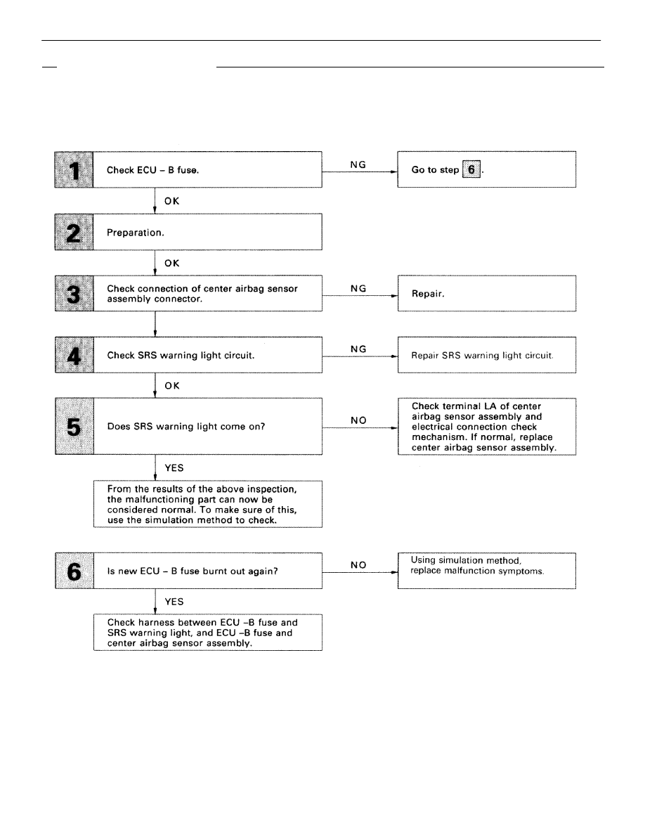
DIAGNOSTIC CHART

DIAGNOSTIC CHART

Troubleshooting  for this system is different for when the SRS warning light does not light up and for when diag-
nostic trouble code 22 is output. Confirm the problem symptoms first before selecting the appropriate trouble-
shooting procedure.
HINT: If SRS warning light does not light up, perform the following troubleshooting:

(See page 

RS–65

)

SUPPLEMENTAL RESTRAINT SYSTEM

TROUBLESHOOTING

RS–103

WIRING DIAGRAM

DIAGNOSTIC CHART

DIAGNOSTIC CHART

HINT: If diagnostic trouble code 22 is output, perform the following troubleshooting:

(See page 

RS–65

).

RS–104

SUPPLEMENTAL RESTRAINT SYSTEM

TROUBLESHOOTING

OK

NG

OK

NG

INSPECTION PROCEDURE

HINT: If SRS warning light does not light up, perform the following troubleshooting:

1

Check ECU–B fuse.

Go to step 


2

Preparation.

P

1.

Disconnect battery negative (–) terminal cable, and
wait at least 90 seconds.

2.

Remove steering wheel pad (See page 

RS–19

).

3.

Disconnect connectors of front passenger airbag
assembly (See page 

RS–32

).

Caution:

Store the steering wheel pad with the

surface facing upward.

3

Check connection of center airbag sensor assembly connector.

Repair.

SUPPLEMENTAL RESTRAINT SYSTEM

TROUBLESHOOTING

RS–105

OK

NG

YES

NO

YES

NO

4

Check SRS warning light circuit.

C

OK

P

1.

Disconnect center airbag sensor assembly.

2.

Connect negative (–) terminal cable to battery.

3.

Turn ignition switch ACC or ON.

Measure voltage LA terminal of harness side connector
of center airbag sensor assembly.

Voltage:

Battery positive voltage.

Repair SRS warning light circuit.

5

Does SRS warning light come on?

C

OK

P

1.

Disconnect negative (–) terminal cable from bat-
tery.

2.

Connect center airbag sensor assembly.

3.

Connect negative (–) terminal cable to battery.

4.

Turn ignition switch ACC or ON.

Check operation of SRS warning light.

SRS warning light comes on.

Check terminal LA of center airbag sensor assembly and
electrical connection check mechanism. If normal, re-
place center airbag sensor assembly.

From the results of the above inspection, the malfunctioning part can now be considered normal. To
make sure of this, use the simulation method to check.

6

Is new ECU–B fuse burnt out again?

Using simulation method, reproduce malfunction symp-
toms (See page 

RS–65

).

Check harness between ECU–B fuse and SRS warning light, and ECU–B fuse and center airbag sensor
assembly.

RS–106

SUPPLEMENTAL RESTRAINT SYSTEM

TROUBLESHOOTING


Content   ..  800  801  802  803   ..