Lexus SC300 / Lexus SC400. Manual - part 684
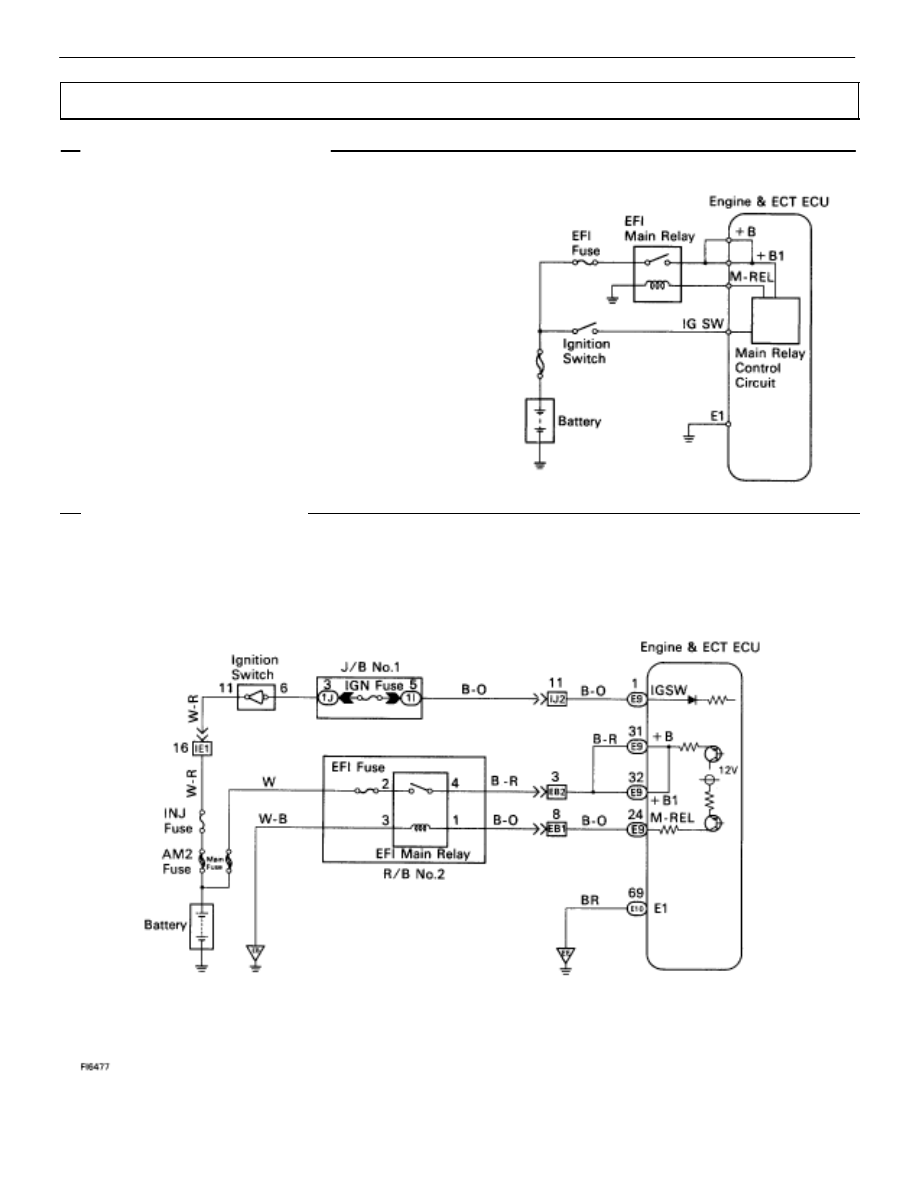
ECU Power Source Circuit
CIRCUIT DESCRIPTION
When the ignition switch is turned on, battery voltage
is applied to the terminal IG SW of the ECU, and the
main relay control circuit in the ECU sends a signal to
the terminal M–REL of the ECU, switching on the
main relay. This signal causes current to flow to the
coil, closing the contacts of the main relay and supply-
ing power to the terminals +B and +B1 of the ECU.
If the ignition switch is turned off, the ECU continues
to switch on the main relay for a maximum of 2 se-
conds for the initial setting of the ISC valve.
DIAGNOSTIC CHART
DIAGNOSTIC CHART
See next page for the DIAGNOSTIC CHART.
WIRING DIAGRAM
TR–124
–
ENGINE TROUBLESHOOTING
Circuit Inspection