Lexus SC300 / Lexus SC400. Manual - part 675
 

  Index      Lexus     Lexus SC300 / Lexus SC400 - service repair manual


Search            


Content   ..  673  674  675  676   ..


Lexus SC300 / Lexus SC400. Manual - part 675


Diag. Code   31

Air Flow Meter Circuit

CIRCUIT DESCRIPTION

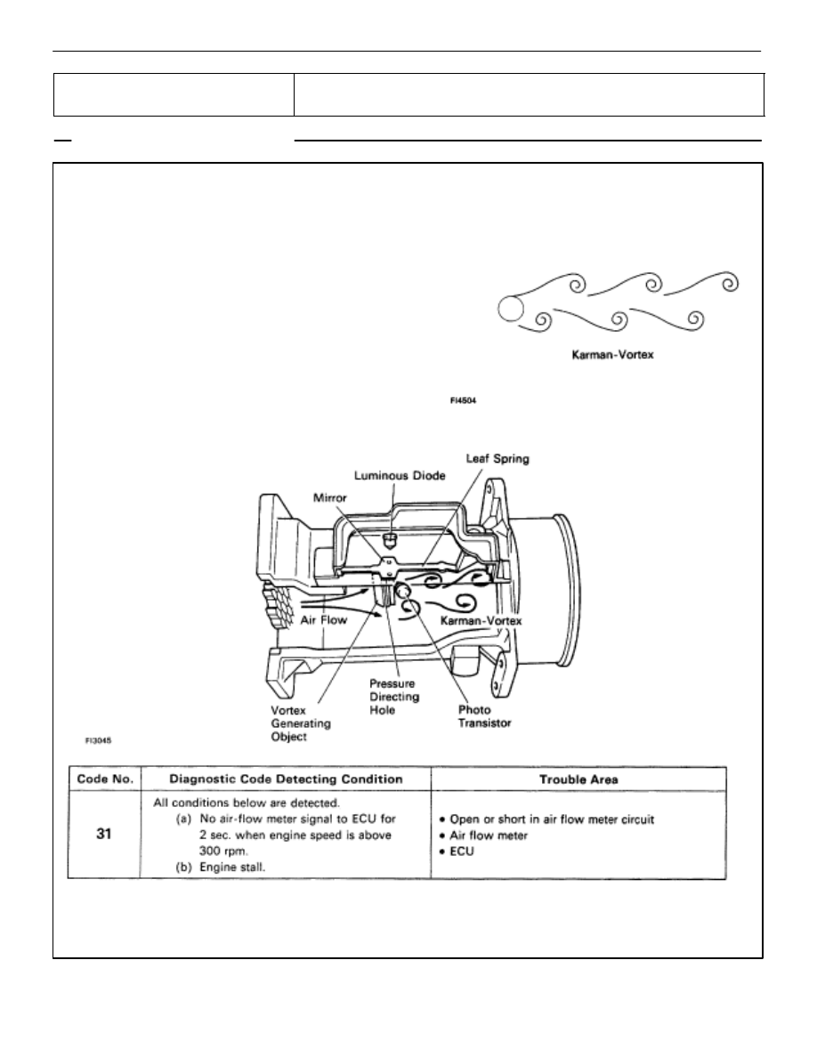
As shown in the figure at right, when a pillar (Vortex
generating body) is placed in the path of a uniform flow,
vortices called Karman–Vortex are generated down-
stream of the object. Using this principle, a vortex gen-
erator is placed inside the air flow meter. By measuring
the frequency of the vortices generated, the ECU can
determine the volume of air flowing through the air flow
meter. The vortices are detected by their exerting pres-
sure on thin metal foil (mirror) surfaces and a light emit-
ting element and light receptor (LED and photo transis-
tor) positioned opposite the mirror which senses the
vibrations in the mirror optically. The ECU uses these
signals mainly for calculation of the basic injection vol-
ume and the basic ignition advance angle.

If the ECU records diagnostic code ”31”, it enters fail safe mode (See page 

TR–22

).

TR–88

ENGINE TROUBLESHOOTING

Circuit Inspection

DIAGNOSTIC CHART

DIAGNOSTIC CHART

WIRING DIAGRAM

Check and replace ECU.

Replace air flow meter.

Check and replace ECU.

Check voltage of air flow meter power source.

Check voltage terminal KS of ECU.

Check for open and short in harness and
connector between air flow meter and ECU.

Check voltage of terminal KS.

Repair or repolace harness or
connector

When diag. code 31 is displayed,
check and replace ECU.

ENGINE TROUBLESHOOTING

Circuit Inspection

TR–89

NG

OK

OK

NG

INSPECTION PROCEDURE

1

Check voltage between terminals KS and E1 of engine & ECT ECU connector.

C

OK

P

Connect the check harness A.
(See page 

TR–30

)

Measure voltage between terminals KS and E1 of en-
gine & ECT ECU connector while engine is cranked.

Voltage:

2.0 – 4.0 V
(Neither 0 V nor 5 V)

When diag. code 31 is displayed, check and replace en-
gine & ECT ECU.

2

Check for open and short in harness and connector between engine & ECT ECU and air flow
meter (See page 

IN–27

).

Repair or replace harness or connector.

TR–90

ENGINE TROUBLESHOOTING

Circuit Inspection

OK

NG

NG

OK

3

Disconnect air flow meter connector and check voltage between terminals KS and E1 of engine
& ECT ECU.

C

OK

P

Diconnect the air flow meter connector.

Turn ignition switch on.

Measure voltage between terminals KS and E1 of en-
gine & ECT ECU.

Voltage:

4 – 6 V

Check and replace ECU.

4

Diconnect air flow meter connector and check voltage between terminals VC and E1 of engine
& ECT ECU.

C

OK

P

Diconnect the air flow meter connector.

Turn ignition switch on.

Measure voltage between terminals VC and E1 of en-
gine & ECT ECU.

Voltage:

4 – 6 V

Replace air flow meter.

Check and replace engine & ECT ECU.

ENGINE TROUBLESHOOTING

Circuit Inspection

TR–91


Content   ..  673  674  675  676   ..