Lexus SC300 / Lexus SC400. Manual - part 637
 

  Index      Lexus     Lexus SC300 / Lexus SC400 - service repair manual


Search            


Content   ..  635  636  637  638   ..


Lexus SC300 / Lexus SC400. Manual - part 637


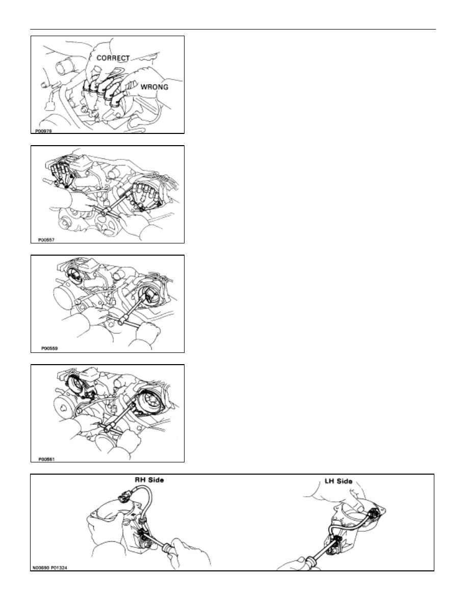
7. DISCONNECT HIGH–TENSION CORDS FROM

DISTRIBUTOR CAPS
Disconnect the high–tension cords at the rubber boot. Do not
pull on the cord.
NOTICE: Pulling or bending the cords may damage the
conductor inside.

8. REMOVE 

DISTRIBUTOR 

CAPS

Loosen the three bolts, and remove the distributor cap. Re-
move the two distributor caps.
HINT: Arrange the distributor caps (RH side and LH side).

9. REMOVE 

DISTRIBUTOR 

ROTORS

Loosen the two bolts, and remove the distributor rotor. Re-
move the two distributor rotors.
HINT: Arrange the distributor rotors (RH side and LH side).

10. REMOVE 

DISTRIBUTOR 

HOUSINGS

(a)  (RH Distributor Housing)

Disconnect the cam position sensor connector.

(b)  Remove the three bolts and distributor housing.

Remove the two distributor housings.

11. 

REMOVE CAM POSITION SENSORS FROM
DISTRIBUTOR HOUSINGS
Remove the bolt, screw and cam position sensor.
Remove the two cam position sensors.

 IGNITION SYSTEM

Distributor

IG–25

INSTALLATION OF DISTRIBUTOR

(See Components on page 

IG–23

)

1.  INSTALL CAM POSITION SENSORS TO DISTRIBUTOR

HOUSINGS
Install the cam position sensor with the bolt and screw. Install
the two cam position sensors.

Torque: 6.4 N

m (65 kgf

cm, 56 in.

lbf)

HINT:

The RH distributor housing is marked with ”R”.

The LH distributor housing is marked with ”L”.

2. 

INSTALL RH DISTRIBUTOR HOUSING
(a)  Install the distributor housing with the three bolts.

Torque: 18 N

m (185 kgf

cm, 13 ft

lbf)

HINT:

The RH distributor housing is marked with ”R”.

Each bolt length is indicated in the illustration.

Bolt length: A 38 mm (1.50 in.)

B 96 mm (3.78 in.)

(b)  Connect the cam position sensor connector.

3. 

INSTALL LH DISTRIBUTOR HOUSING
(a)  Install the distributor housing with the three bolts.

Torque: 18 N

m (185 kgf

cm, 13 ft

lbf)

HINT:

The LH distributor housing is marked with ”L”.

Each bolt length is indicated in the illustration.

Bolt length: A 38 mm (1.50 in.)

B 80 mm (3.15 in.)

4. INSTALL 

DISTRIBUTOR 

ROTORS

(a)  Align the protrusion of the distributor rotor with the

groove of the camshaft timing pulley.

(b)  Install the distributor rotor with the two bolts. Install the

two distributor rotors.

Torque: 3.8 N

m (39 kgf

cm, 34 in.

lbf)

IG–26

 IGNITION SYSTEM

Distributor

5. INSTALL 

DISTRIBUTOR 

CAPS

Install the distributor cap with the three bolts. Install the two
distributor caps.

Torque: 3.8 N

m (39 kgf

cm, 34 in.

lbf)

6.  CONNECT HIGH–TENSION CORDS TO DISTRIBUTOR

CAPS
Connect the ten high–tension cords.
NOTICE: Connect the high–tension cord by pressing on
the correct place as shown in the illustration.
If not done this way, the high–tension cord will interfere with
the camshaft timing pulley.

7. 

INSTALL RH NO.2 TIMING BELT COVER
(a)  Install the four gaskets to the timing belt cover.
(b)  Install the connector grommet to the timing belt cover.
(c)  Install the timing belt cover with the five bolts.

Torque: 16 N

m (160 kgf

cm, 12 ft

lbf)

HINT (12 mm head bolt): Use bolts 106 mm (4.17 in.) in
length.
(d)  Install the wire clamp to the timing belt cover.
(e) Install 

the 

cam position sensor wire to the wire clamp on

the timing belt cover.

(f) 

Install the cam position sensor connector to the ignition
coil bracket.

8. 

INSTALL LH NO.2 TIMING BELT COVER
(a)  Install the two gaskets to the timing belt cover.
(b)  Run the cam position sensor wire through the timing belt

cover hole.

(c)  Install the timing belt cover and connector bracket with

the three bolts.

(d)  Connect the cam position sensor connector.
(e)  Install the cam position sensor connector to the

connector bracket.

(f) Install 

the 

cam position sensor wire to the wire clamp on

the timing belt cover.

(g)  Install the connector grommet to the timing belt cover.

 IGNITION SYSTEM

Distributor

IG–27

9. 

INSTALL DRIVE BELT IDLER PULLEY
Install the idler pulley and cover plate with the pulley bolt.

Torque: 37 N

m (380 kgf

cm, 27 ft

lbf)

10.  INSTALL NO.3 TIMING BELT COVERS

(See steps 5 to 9 and 11 on pages 

IG–17

 to 19)

11.  CONNECT RADIATOR HOSE TO WATER INLET
12.  CONNECT CABLE TO NEGATIVE TERMINAL OF

BATTERY

13.  FILL ENGINE WITH COOLANT (See page 

CO–6

)

14.  WARM UP ENGINE

Allow the engine to warm up to normal operating tempera-
ture.

15. CONNECT 

TACHOMETER

Connect the tester probe of a tachometer to terminal IG


 of

the check (”DIAGNOSIS”) connector.
HINT: Set the tachometer to the 4–cylinder range.
NOTICE:

Never allow the tachometer tester probe to touch ground

as it could result in damage to the igniter and/or ignition

coil.

As some tachometers are not compatible with this

ignition system, we recommend that you confirm the

compatibility of your unit before use.

16.  CHECK IGNITION TIMING

(a)  Using SST, connect terminals TE1 and E1 of the check

(”DIAGNOSIS”) connector.

SST 09843–18020

(b) Connect the tester probe of a timing light to the

high–tension cord for No.6 cylinder.

IG–28

 IGNITION SYSTEM

Distributor


Content   ..  635  636  637  638   ..