Lexus SC300 / Lexus SC400. Manual - part 534
REPLACEMENT OF CRANKSHAFT
FRONT OIL SEAL
(See page
)
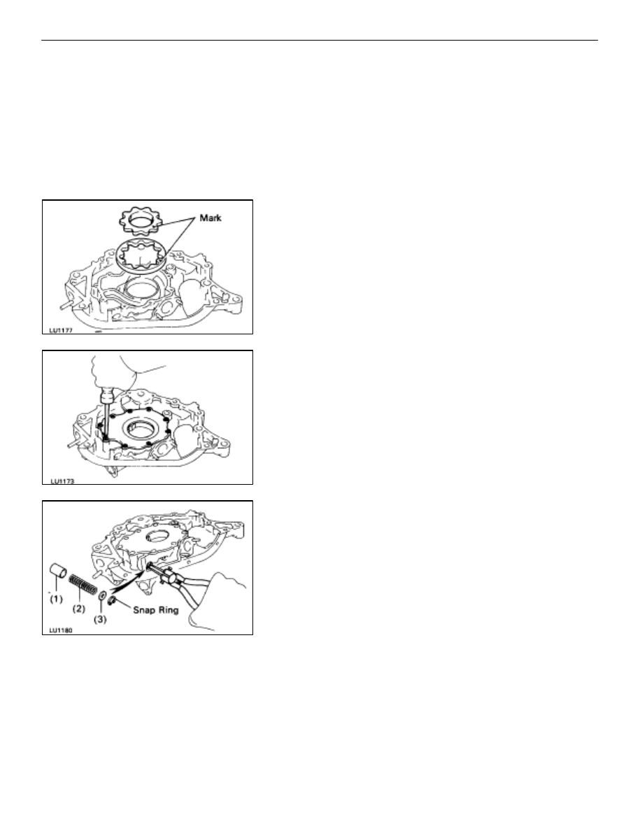
ASSEMBLY OF OIL PUMP
(See Components on page
1.
INSTALL DRIVE AND DRIVEN ROTORS
(a) Place
the drive and driven rotors into oil pump body with
the mark facing upward.
(b) Install the pump body cover with the nine screws.
Torque: 10 N
⋅
m (105 kgf
⋅
cm, 8 ft
⋅
lbf)
2.
INSTALL RELIEF VALVE
(a) Insert the following parts into the oil pump body hole:
(1) Relief
valve
(2) Compression
spring
(3) Retainer
(b) Using snap ring pliers, install the snap ring.
LU–14
–
LUBRICATION SYSTEM
Oil Pump