Lexus SC300 / Lexus SC400. Manual - part 528


  Index      Lexus     Lexus SC300 / Lexus SC400 - service repair manual


Search            


Content   ..  526  527  528  529   ..


Lexus SC300 / Lexus SC400. Manual - part 528


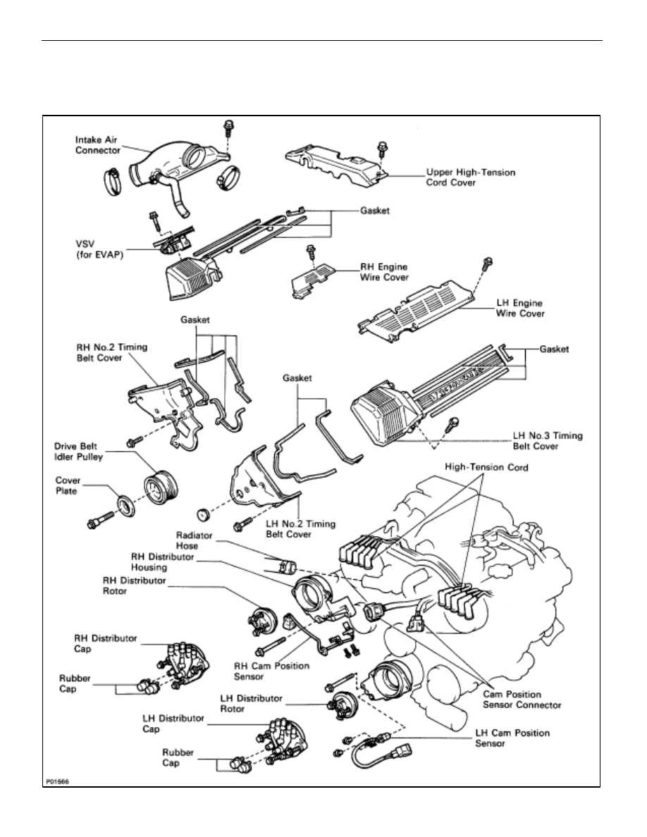
DISTRIBUTOR

COMPONENTS FOR REMOVAL AND
INSTALLATION

 IGNITION SYSTEM

Distributor

IG–23

REMOVAL OF DISTRIBUTOR

(See Components on page 

IG–23

)

1. 

DRAIN ENGINE COOLANT (See page 

CO–6

)

2. 

DISCONNECT RADIATOR HOSE FROM WATER INLET

3. 

REMOVE NO.3 TIMING BELT COVERS
(See steps 1 to 8 on pages 

IG–11

 to 13)

4. 

REMOVE DRIVE BELT IDLER PULLEY
Remove the pulley bolt, cover plate and idler pulley.

5. 

REMOVE RH NO.2 TIMING BELT COVER
(a)  Disconnect the cam position sensor connector from the

ignition coil bracket.

(b) Disconnect 

the 

cam position sensor wire from the clamp

on the timing belt cover.

(c)  Remove the five mounting bolts.
(d)  Disconnect the connector grommet from the timing belt

cover.

(e)  Disconnect the wire clamp from the timing belt cover,

and remove the timing belt cover and four gaskets.

6. 

REMOVE LH NO.2 TIMING BELT COVER
(a) Disconnect 

the 

cam position sensor wire from the clamp

on the timing belt cover.

(b)  Disconnect the cam position sensor connector.
(c)  Remove the three mounting bolts.
(d)  Disconnect the connector grommet from the timing belt

cover, and remove the timing belt cover and two
gaskets.

IG–24

 IGNITION SYSTEM

Distributor

7. DISCONNECT HIGH–TENSION CORDS FROM

DISTRIBUTOR CAPS
Disconnect the high–tension cords at the rubber boot. Do not
pull on the cord.
NOTICE: Pulling or bending the cords may damage the
conductor inside.

8. REMOVE 

DISTRIBUTOR 

CAPS

Loosen the three bolts, and remove the distributor cap. Re-
move the two distributor caps.
HINT: Arrange the distributor caps (RH side and LH side).

9. REMOVE 

DISTRIBUTOR 

ROTORS

Loosen the two bolts, and remove the distributor rotor. Re-
move the two distributor rotors.
HINT: Arrange the distributor rotors (RH side and LH side).

10. REMOVE 

DISTRIBUTOR 

HOUSINGS

(a)  (RH Distributor Housing)

Disconnect the cam position sensor connector.

(b)  Remove the three bolts and distributor housing.

Remove the two distributor housings.

11. 

REMOVE CAM POSITION SENSORS FROM
DISTRIBUTOR HOUSINGS
Remove the bolt, screw and cam position sensor.
Remove the two cam position sensors.

 IGNITION SYSTEM

Distributor

IG–25

INSTALLATION OF DISTRIBUTOR

(See Components on page 

IG–23

)

1.  INSTALL CAM POSITION SENSORS TO DISTRIBUTOR

HOUSINGS
Install the cam position sensor with the bolt and screw. Install
the two cam position sensors.

Torque: 6.4 N

m (65 kgf

cm, 56 in.

lbf)

HINT:

The RH distributor housing is marked with ”R”.

The LH distributor housing is marked with ”L”.

2. 

INSTALL RH DISTRIBUTOR HOUSING
(a)  Install the distributor housing with the three bolts.

Torque: 18 N

m (185 kgf

cm, 13 ft

lbf)

HINT:

The RH distributor housing is marked with ”R”.

Each bolt length is indicated in the illustration.

Bolt length: A 38 mm (1.50 in.)

B 96 mm (3.78 in.)

(b)  Connect the cam position sensor connector.

3. 

INSTALL LH DISTRIBUTOR HOUSING
(a)  Install the distributor housing with the three bolts.

Torque: 18 N

m (185 kgf

cm, 13 ft

lbf)

HINT:

The LH distributor housing is marked with ”L”.

Each bolt length is indicated in the illustration.

Bolt length: A 38 mm (1.50 in.)

B 80 mm (3.15 in.)

4. INSTALL 

DISTRIBUTOR 

ROTORS

(a)  Align the protrusion of the distributor rotor with the

groove of the camshaft timing pulley.

(b)  Install the distributor rotor with the two bolts. Install the

two distributor rotors.

Torque: 3.8 N

m (39 kgf

cm, 34 in.

lbf)

IG–26

 IGNITION SYSTEM

Distributor


Content   ..  526  527  528  529   ..