Lexus SC300 / Lexus SC400. Manual - part 475
 

  Index      Lexus     Lexus SC300 / Lexus SC400 - service repair manual


Search            


Content   ..  473  474  475  476   ..


Lexus SC300 / Lexus SC400. Manual - part 475


PRECAUTIONS

1. 

Always use new gaskets when replacing the fuel tank or
component part.

2. 

Apply the proper torque to all parts tightened.

INSPECTION OF FUEL LINES AND
CONNECTIONS

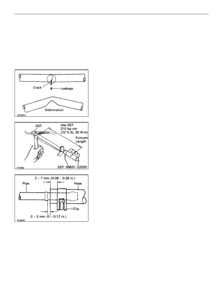
(a)  Inspect the fuel lines and connections for cracks,

leakage or deformation.

(b)  Inspect the fuel tank vapor vent system hoses and

connections for looseness, kinks or damage.

(c)  Inspect the fuel tank for deformation, cracks, fuel

leakage or tank band looseness.

(d)  Check the filter neck for damage or fuel leakage.

(e) Hose and tube connections are as shown in the

illustration.

If a problem is found, repair or replace the parts as necessary.

FI–62

EFI SYSTEM   –   Fuel System (Fuel Tank and Lines)

AIR INDUCTION SYSTEM
Air Flow Meter

ON–VEHICLE INSPECTION

INSPECT RESISTANCE OF AIR FLOW METER

(a)  Disconnect the air flow meter connector.
(b)  Using an ohmmeter, measure the resistance between

terminals THA and E2.

Between

Resistance

Temperature

Between
terminals

Resistance

Tem erature

terminals

10–20 k


–20

°

C (–4

°

F)

4–7 k


9

°

C (32

°

F)

THA–E2

2–3 k


20

°

C (68

°

F)

0.9–1.3 k


40

°

C (104

°

F)

0.4–0.7 k


60

°

C (140

°

F)

If the resistance is not as specified, replace the air flow meter.
(c)  Reconnect the air flow meter connector.

FI–63

                                –   Air Induction System (Air Flow Meter)

EFI SYSTEM

COMPONENTS

REMOVAL OF AIR FLOW METER

1. 

DISCONNECT CABLE FROM NEGATIVE TERMINAL OF
BATTERY
CAUTION: Work must be started after approx. 20 se-
conds or longer from the time the ignition switch is
turned to the ”LOCK” position and the negative (–) termi-
nal cable is disconnected from the battery.

2. 

DISCONNECT AIR FLOW METER CONNECTOR
(a)  Disconnect the air flow meter connector.
(b)  Disconnect the wire clamp from the clamp bracket on

the air flow meter.

3. 

REMOVE AIR CLEANER CASE AND AIR FLOW METER
ASSEMBLY
(a)  Loosen the hose clamp.
(b)  Remove the four mounting bolts.
(c)  Disconnect the air cleaner hose from the air flow meter.
(d)  Disconnect the air duct from the air cleaner case, and

remove the  air cleaner case  and  air  flow meter
assembly.

FI–64

EFI SYSTEM   –   Air Induction System (Air Flow Meter)

4. 

REMOVE AIR FLOW METER FROM AIR CLEANER CASE
Remove the four bolts and air flow meter and gasket.

INSPECTION OF AIR FLOW METER

INSPECT AIR FLOW METER

Check that the honey–combed is neither deformed nor
damaged.
If necessary, replace the air flow meter.

INSTALLATION OF AIR FLOW METER

(See Components on page 

FI–64

)

1. 

INSTALL AIR FLOW METER FROM AIR CLEANER CASE
Install a new gasket and the air flow meter with the four bolts.

Torque: 10 N

m (100 kgf

cm, 7 ft

lbf)

2.  INSTALL AIR CLEANER CAP AND AIR FLOW METER

ASSEMBLY
(a)  Connect the air cleaner case to the air duct.
(b)  Connect the air flow meter to the air cleaner hose.
(c)  Install the air cleaner and air flow meter assembly with

the four bolts.

(d)  Tighten the hose clamp.

3. 

CONNECT AIR FLOW METER CONNECTOR
(a)  Connect the air flow meter connector.
(b) Install 

the wire clamp to the clamp bracket on the air flow

meter.

4.  CONNECT CABLE FROM NEGATIVE TERMINAL OF

BATTERY

FI–65

EFI SYSTEM   –   Air Induction System (Air Flow Meter)


Content   ..  473  474  475  476   ..