Lexus SC300 / Lexus SC400. Manual - part 359
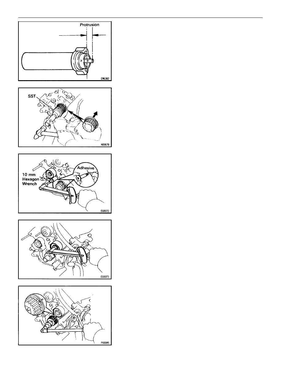
(c) Measure
the protrusion of the push rod from the housing end.
Protrusion:
10.5 – 11.5 mm (0.413 – 0.453 in.)
If the protrusion is not as specified, replace the tensioner.
EG21R–02
TIMING BELT INSTALLATION
See Components for Removal and Installation:
1.
INSTALL CRANKSHAFT TIMING PULLEY
(a) Align the timing pulley set key with the key groove of the
pulley.
(b) Using SST and a hammer, tap in the timing pulley, facing the
flange side inward.
SST 09223–46011
2.
INSTALL NO.1 IDLER PULLEY
(a) Apply adhesive 2 or 3 threads of the pivot bolt.
Adhesive:
Part No. 08833–00080, THREE BOND 1344,
LOCTITE 242 or equivalent
(b) Using a 10 mm hexagon wrench, install the plate washer and
idler pulley with the pivot bolt.
Torque: 34 N
⋅
m (350 kgf
⋅
cm, 25 ft
⋅
lbf)
(c) Check that the pulley bracket moves smoothly.
3.
INSTALL NO.2 IDLER PULLEY
(a) Install the idler pulley with the bolt.
Torque: 34 N
⋅
m (350 kgf
⋅
cm, 25 ft
⋅
lbf)
(b) Check that the idler pulley moves smoothly.
4.
TEMPORARILY INSTALL TIMING BELT
NOTICE: The engine should be cold.
(a) Using
the crankshaft pulley bolt, turn the crankshaft and align
the timing marks of the crankshaft timing pulley and oil pump
body.
–
1UZ–FE ENGINE
ENGINE MECHANICAL
EG–59