Lexus SC300 / Lexus SC400. Manual - part 340
 

  Index      Lexus     Lexus SC300 / Lexus SC400 - service repair manual


Search            


Content   ..  338  339  340  341   ..


Lexus SC300 / Lexus SC400. Manual - part 340


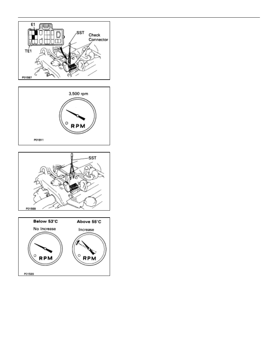
INSPECTION OF EGR SYSTEM (USA
Spec.)
INSPECT SYSTEM OPERATION

(a)  Using SST, connect terminals TE1 and E1 of the check

(”DIAGNOSIS”) connector.

SST 09843–18020

(b)  Keep the engine at 3,500 rpm.

(c)  Set the transmission shift lever to the ”N” position.
(d)  Remove the SST from the check connector.
SST 09843–18020

(e)  Check whether the engine rpm increases 100–300 rpm

under the following conditions.

Coolant temp.

Below 53

°

C (127

°

F) No increase

Above 55

°

C (131

°

F) Increases

EMISSION CONTROL SYSTEMS

Exhaust Gas Recirculation (EGR) System

EC–17

INSPECTION OF EGR SYSTEM
(Exc. USA Spec.)

1. CHECK 

AND 

CLEAN 

FILTERS 

IN 

EGR 

VACUUM

MODULATOR
(a)  Remove the cap and filter.
(b)  Check the filter for contamination or damage.
(c)  Using compressed air, clean the filters.
(d)  Reinstall the filter and cap.
HINT: Install the filter with the coarser surface facing the at-
mospheric side (outward).

2. 

INSPECT SYSTEM OPERATION
(a)  Using SST, connect terminals TE1 and E1 of the check

(”DIAGNOSIS”) connector.

SST 09843–18020

(b)  Keep the engine at 3,500 rpm.

(c)  Set the transmission shift lever to the ”N” position.
(d)  Remove the SST from the check connector.
SST 09843–18020

(e)  Check whether the engine rpm increases 100–300 rpm

under the following conditions:

Coolant temp.

Below 53

°

C (127

°

F) No increase

Above 55

°

C (131

°

F) Increases

EC–18

EMISSION CONTROL SYSTEMS

Exhaust Gas Recirculation (EGR) System

INSPECTION OF VSV (Exc. USA Spec.)

1. 

DISCONNECT CABLE FROM NEGATIVE TERMINAL OF
BATTERY
CAUTION: Work must be started after approx. 20 se-
conds or longer from the time the ignition switch is
turned to the ”LOCK” position and the negative (–) termi-
nal cable is disconnected from the battery.

2. REMOVE 

VSV

(a)  Disconnect the VSV connector.
(b)  Disconnect the following hoses:

(1)  Vacuum hose (from EGR valve) from VSV
(2)  Vacuum hose (from EGR vacuum modulator) from

VSV

(c)  Remove the bolt and VSV.

3. INSPECT 

VSV

A.  Inspect VSV for open circuit

Using an ohmmeter, check that there is continuity between
the terminals.

Resistance (Cold): 33–39 


If there is no continuity, replace the VSV.

B.  Inspect VSV for ground

Using an ohmmeter, check that there is no continuity be-
tween each terminal and the body.
If there is continuity, replace the VSV.

C.  Inspect VSV operation

(a)  Check that the air flows from ports E to G.

EMISSION CONTROL SYSTEMS

Exhaust Gas Recirculation (EGR) System

EC–19

(b)  Apply battery voltage across the terminals.
(c)  Check that the air flows from port E to the filter.
If operation is not as specified, replace the VSV.

4. REINSTALL 

VSV

(a)  Install the VSV with the bolt.

Torque: 18 N

m (185 kgf

cm, 13 ft

lbf)

(b)  Connect the following hoses:

(1)  Vacuum hose (from EGR valve) to VSV
(2)  Vacuum hose (from EGR vacuum modulator) to

VSV

(c)  Connect the VSV connector.

5.  RECONNECT CABLE TO NEGATIVE TERMINAL OF

BATTERY

INSPECTION OF EGR VACUUM
MODULATOR (Exc. USA Spec.)

1.  DISCONNECT VACUUM HOSES FROM EGR VACUUM

MODULATOR
Disconnect the three vacuum hoses from ports P, Q and R of
the EGR vacuum modulator.

2. 

INSPECT EGR VACUUM MODULATOR OPERATION
(a)  Block ports P and R with your finger.
(b)  Blow air into port Q, and check that the air passes

through to the air filter side freely.

(c)  Start the engine, and maintain speed at 2,500 rpm.
(d)  Repeat the above test. Check that there is a strong

resistance to air flow.

3. RECONNECT 

VACUUM 

HOSES 

TO 

EGR 

VACUUM

MODULATOR
Connect the three vacuum hoses to the proper locations.

EC–20

EMISSION CONTROL SYSTEMS

Exhaust Gas Recirculation (EGR) System


Content   ..  338  339  340  341   ..