Lexus SC300 / Lexus SC400. Manual - part 337
 

  Index      Lexus     Lexus SC300 / Lexus SC400 - service repair manual


Search            


Content   ..  335  336  337  338   ..


Lexus SC300 / Lexus SC400. Manual - part 337


INSPECTION OF VSV

1. 

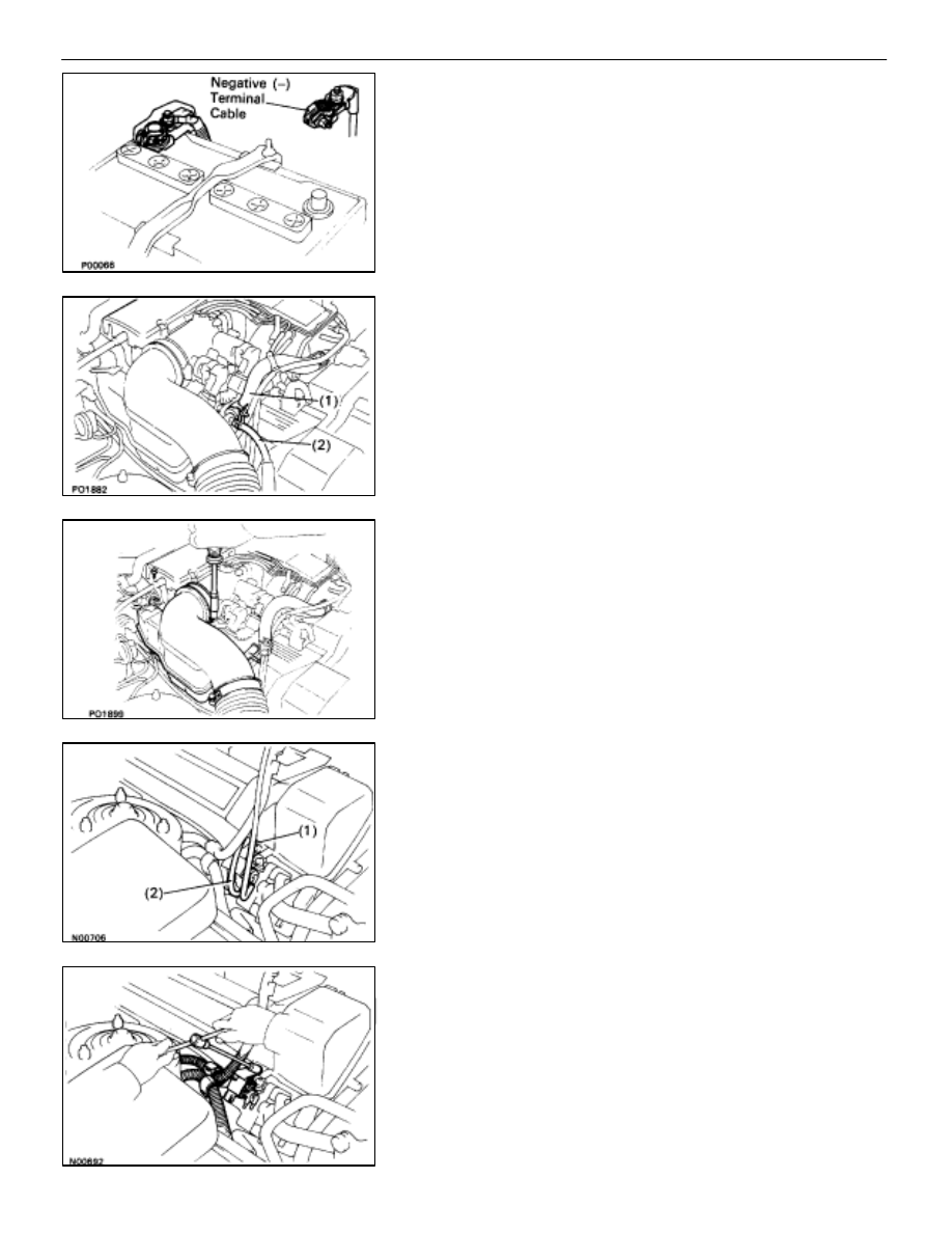
DISCONNECT CABLE FROM NEGATIVE TERMINAL OF
BATTERY
CAUTION: Work must be started after approx. 20 se-
conds or longer from the time the ignition switch is
turned to the ”LOCK” position and the negative (–) termi-
nal cable is disconnected from the battery.

2. 

REMOVE INTAKE AIR CONNECTOR
(a)  Disconnect the following hoses:

(1)  Air hose (from ISC valve) from intake air connector
(2)  Air hose (from PS air control valve) from intake air

connector

(b)  Remove the bolt holding the intake air connector to the

cylinder head cover.

(c)  Loosen the two hose clamps.
(d)  Disconnect the intake air connector from the throttle

body and air cleaner hose, and remove the intake air
connector.

3. REMOVE 

VSV

(a)  Disconnect the VSV connector.
(b)  Disconnect the following hoses:

(1)  Vacuum hose (from vacuum pipe) from VSV
(2)  Vacuum hose (from charcoal canister) from VSV

(c)  Remove the two bolts and VSV from the cylinder head.
(d)  Disconnect the two wire clamps from the VSV bracket,

and remove the VSV.

EMISSION CONTROL SYSTEMS

Fuel Evaporative Emission Control (EVAP) System

EC–11

4. INSPECT 

VSV

A.

Inspect VSV for open circuit
Using an ohmmeter, check that there is continuity between
the terminals.

Resistance (Cold): 30–34 


If there is no continuity, replace the VSV.

B.  Inspect VSV for ground

Using an ohmmeter, check that there is no continuity be-
tween each terminal and the body.
If there is continuity, replace the VSV.

C.  Inspect VSV operation

(a)  Check that the air flows with difficulty from ports E to F.

(b)  Apply battery voltage across the terminals.
(c)  Check that the air flows without resistance from port E

to F.

If operation is not as specified, replace the VSV.

5. REINSTALL 

VSV

(a)  Install the VSV with the two bolts.
(b)  Connect the two wire clamps to the VSV bracket.

EC–12

EMISSION CONTROL SYSTEMS

Fuel Evaporative Emission Control (EVAP) System

(c)  Connect the following hoses:

(1)  Vacuum hose (from vacuum pipe) to VSV
(2)  Vacuum hose (from charcoal canister) to VSV

(d)  Connect the VSV connector.

6. 

REINSTALL INTAKE AIR CONNECTOR
(a)  Connect the end portions of the intake air connector to

the throttle body and air cleaner hose.

(b)  Tighten the two hose clamps.
(c)  Install the bolt holding the intake air connector to the

cylinder head cover.

(d)  Connect the following hoses:

(1)  Air hose (from ISC valve) to intake air connector
(2) Air 

hose (from PS air control valve) to intake air con-

nector

7. RECONNECT 

CABLE 

TO 

NEGATIVE 

TERMINAL 

OF

BATTERY

INSPECTION OF CHECK VALVE

1. 

REMOVE CHECK VALVE
(a)  Disconnect the grommet on the check valve from the

bracket.

(b)  Remove the check valve from the hose end on the

charcoal canister.

(c)  Remove the grommet from the check valve.

2. 

INSPECT CHECK VALVE
(a)  Check that air flows from the yellow port to the black

port.

(b)  Check that air does not flow from the black port to the

yellow port.

If operation is not as specified, replace the check valve.

EMISSION CONTROL SYSTEMS

Fuel Evaporative Emission Control (EVAP) System

EC–13

3. REINSTALL 

CHECK 

VALVE

HINT: Reinstall the check valve with the black port facing the
charcoal canister side.
(a)  Install the grommet to the check valve.
(b)  Install the check valve to the hose end on the charcoal

canister.

(c)  Install the grommet on the check valve to the bracket.

EC–14

EMISSION CONTROL SYSTEMS

Fuel Evaporative Emission Control (EVAP) System


Content   ..  335  336  337  338   ..