Lexus SC300 / Lexus SC400. Manual - part 325
4.
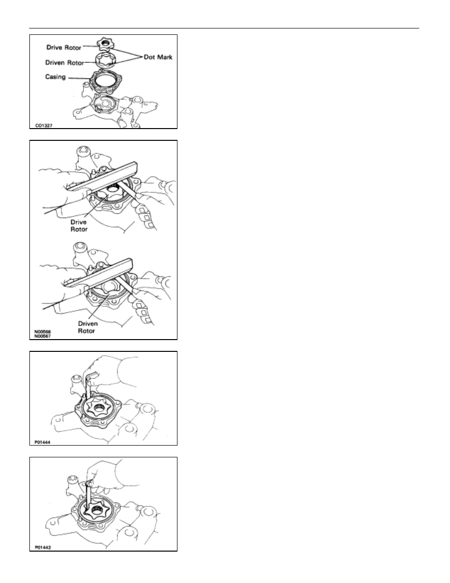
INSPECT DRIVE AND DRIVEN ROTORS
A.
Install casing and rotors to rear housing
Face the dot mark of the rotors upward.
B.
Inspect rotor side clearance
HINT: Before measuring the clearance, remove one side of
the rotor.
Using a feeler gauge and precision straight edge, measure
the clearance between the rotor and precision straight edge.
Standard side clearance:
Drive rotor 0.02 mm (0.0008 in.)
Driven rotor 0.03 mm (0.0012 in.)
Maximum side clearance:
Drive rotor 0.03 mm (0.0012 in.)
Driven rotor 0.04 mm (0.0016 in.)
If the clearance is greater than maximum, replace the rotors
as a set. If necessary, replace the housings.
C.
Inspect rotor body clearance
Using a feeler gauge, measure the clearance between the
driven rotor and casing.
Standard body clearance: 0.05–0.09 mm
(0.0020–0.0035 in.)
Maximum body clearance: 0.10 mm (0.0039 in.)
If the clearance is greater than maximum, replace the rotors
as a set. If necessary, replace the casing.
D.
Inspect rotor tip clearance
Using a feeler gauge, measure the clearance of all the six
drive rotor tips between the drive and driven rotors.
Standard tip clearance: 0.02 mm (0.0008 in.)
Maximum tip clearance: 0.03 mm (0.0012 in.)
If the clearance is greater than maximum, replace the rotors
as a set.
E.
Remove rotors and causing from rear housing
–
COOLIING SYSTEM
Electronically Controlled Hydraulic
Cooling Fan (Hydraulic Pump)
CO–35