Lexus SC300 / Lexus SC400. Manual - part 288
 

  Index      Lexus     Lexus SC300 / Lexus SC400 - service repair manual


Search            


Content   ..  286  287  288  289   ..


Lexus SC300 / Lexus SC400. Manual - part 288


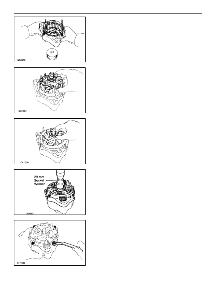
ASSEMBLY OF ALTERNATOR

(See Components on page 

CH–10

)

1. 

PLACE RECTIFIER END FRAME ON PULLEY

2. 

INSTALL ROTOR TO RECTIFIER END FRAME

3. 

INSTALL RECTIFIER END FRAME
(a)  Place the alternator washer on the rotor.

(b)  Using a 29 mm socket wrench and press, slowly press

in the rectifier end frame.

(c)  Install the four mounting nuts.

CHARGING SYSTEM

Alternator

CH–17

4. INSTALL 

PULLEY

(a)  Install the pulley to the rotor shaft by tightening the

pulley nut by hand.

(b)  Hold SST (A) with a torque wrench, and tighten SST (B)

clockwise to the specified torque.

SST 09820–63010

Torque: 39 N

m (400 kgf

cm, 29 ft

lbf)

(c)  Check that SST (A) is secured to the pulley shaft.

(d) As 

shown in the illustration, mount SST (C) in a vise, and

install the alternator to SST (C).

(e)  To torque the pulley nut, turn SST (A) in the direction

shown in the illustration.

Torque: 110 N

m (1,125 kgf

cm, 81 ft

lbf)

(f)  Remove the alternator from SST (C).
(g)  Turn SST (B) and remove SST (A and B).

5. 

INSTALL RECTIFIER HOLDER
(a)  Place the seal plate on the rectifier end frame.

(b)  Install the four rubber insulators on the lead wires.

(c)  Install the rectifier holder with the four screws.

CH–18

CHARGING SYSTEM

Alternator

6. 

INSTALL IC REGULATOR AND BRUSH HOLDER
(a)  Place the IC regulator together and brush holder on the

rectifier end frame.

NOTICE: Be careful of the holder installation direction.
(b) Install 

the 

five 

mounting screws until there is a clearance

of approx. 1 mm (0.04 in.) between the brush holder and
connector.

(c)  Place the brush holder cover on the brush holder.

7. 

INSTALL REAR END COVER
(a)  Install the end cover with the three nuts.

(b)  Install the terminal insulator with the nut.

8. CHECK 

THAT 

ROTOR 

ROTATES 

SMOOTHLY

CHARGING SYSTEM

Alternator

CH–19

INSTALLATION OF ALTERNATOR

(See Components on page 

CH–9

)

1. INSTALL 

ALTERNATOR

(a)  Install the alternator and A/T oil cooler bracket with the

bolt and nut.

Torque: 37 N

m (380 kgf

cm, 27 ft

lbf)

(b)  Connect the alternator connector.
(c)  Connect the alternator wire with the nut and cap.

2. 

INSTALL DRIVE BELT
Install the drive belt by turning the drive belt tensioner coun-
terclockwise.
HINT: The pulley bolt for the belt tensioner has a left–hand
thread.

3.  CONNECT CABLE TO NEGATIVE TERMINAL OF

BATTERY

4. 

PERFORM ON–VEHICLE INSPECTION
(See steps 6 to 8 on pages 

CH–6

 to 8)

5. 

INSTALL ENGINE UNDER COVER

CH–20

CHARGING SYSTEM

Alternator


Content   ..  286  287  288  289   ..