Lexus SC300 / Lexus SC400. Manual - part 228
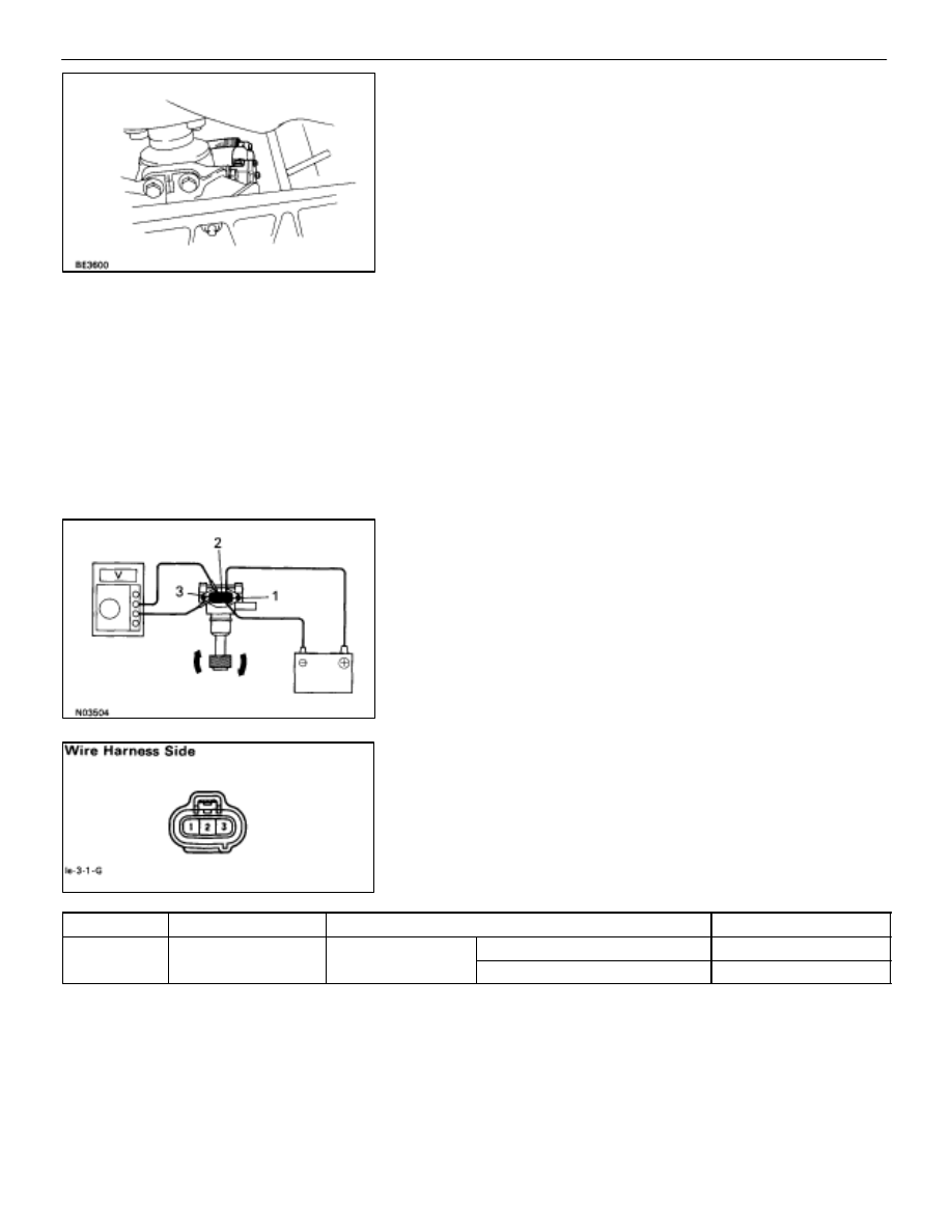
(Speed Sensor)
REMOVAL AND INSTALLATION OF
SPEED SENSOR
1.
REMOVE SPEED SENSOR
(a) Jack up the vehicle.
(b) Disconnect connector and control rod.
(c) Remove a bolt and sensor.
2.
INSTALL SPEED SENSOR
For installation, follow the removal procedure in reverse.
INSPECTION OF SPEED SENSOR
INSPECT SPEED SENSOR
(Operation)
(a) Connect the positive (+) lead from battery to terminal 1
and negative (–) lead to terminal 2.
(b) Connect the positive (+) lead from tester to terminal 3
and negative (–) lead to terminal 2.
(c) Revolve
shaft.
(d) Check that there is voltage change from approx. 0V to
11V or more between terminal 2 and 3.
HINT: The voltage change should be 4 times per each revolu-
tion of the speed sensor shaft.
If operation is not as specified, replace the sensor.
(Sensor circuit)
Disconnect connector from sensor and inspect the connector
on wire harness side as shown.
Check for
Tester connection
Condition
Specified value
Voltage
1 Ground
Ignition switch
ON
Battery positive voltage
g
1–Ground
Ignition switch
position
LOCK or ACC
No voltage
If circuit is not as specified, inspect power source or wire
harness.
–
BODY ELECTRICAL SYSTEM
Combination Meter
BE–110