Lexus SC300 / Lexus SC400. Manual - part 204
 

  Index      Lexus     Lexus SC300 / Lexus SC400 - service repair manual


Search            


Content   ..  202  203  204  205   ..


Lexus SC300 / Lexus SC400. Manual - part 204


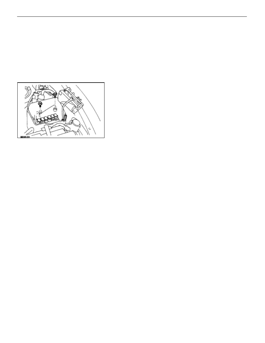
REPLACEMENT OF RELAY BLOCK NO. 2
(B) IN RELAY BLOCK NO. 2

1. 

REMOVE RELAY BLOCK NO. 2 (B)

(a)  Disconnect the battery terminals.

CAUTION: Work must be started after approx. 20 se-
conds or longer from the time the ignition switch is
turned to the ”LOCK” position and negative (–) terminal
cable is disconnected from the battery.

(b)  Remove the relay block No. 2 cover.
(c)  Remove the relay block No. 2 lower cover.

2. 

INSTALL RELAY BLOCK NO. 2 (B)
For installation follow the removal procedure in reverse.

BODY ELECTRICAL SYSTEM

Power Source

BE–17

Description

The power source supplies power to each of the vehicle’s electrical devices. It is composed of the battery, fuses
and relays, which are located centrally at relay block No. 2 and relay block No. 6 in the engine compartment
and junction block No. 1 relay block No. 4 and relay block No. 5 in the cabin near the driver’s feet.

Related systems for each Fuse

No.

Part Name

Related Systems or Parts

1

IGN


 Charging System


 AIR–BAG System

1

IGN


 Engine

2

ST


 Starter

3

WIPER


 Wiper and Washer System

4

HTR


 Defogger System


 A/C System

5

ENGINE


 Charging System

6

RADIO NO. 2


 Audio System


 Power Mirror System


 Cigarette Lighter


 A/C System

7

CIG


 Combination Meter System


 AIR–BAG System

7

CIG


 Shift Lock System


 Theft Deterrent System


 TEL System

8

STOP


 Stop Light System


 Cruise Control System

9

TURN


 Turn Signal and Hazard

   Warning Light System


 Cornnering Light System

10

MIR HTR


 Mirror Heater System

11

PANEL


 Illumination Light System

12

ECU–B


 Combination Meter System


 AIR–BAG System


 Combination Meter System


 ECT System

13

GAUGE


 Back–Up Light


 Transmission Indicator


 Light Failare Sensor


 ABS and TRAC


 Power Seat System


 Door Lock Control System


 TEL System


 Shift Lock System

14

ECU–IG


 Radiator Fan


 Auto Antenna


 Electric Tension Reducer System


 Power Steering


 Auto–Tilt away Steering


 Cruise Control System

15

TAIL


 Taillight System


 Side Marker

15

TAIL


 Clearance Light

16

DOOR


 Power Seat System


 Luggage Door Opener

16

DOOR


 Door Lock Control System


 Fuel Lid Opener System

17

IG SW

Upstream of ECU–IG, ENGINE, WIP, HTR, TURN, GAUGE, and ST Fuse

18

PWR


 Power Window System


 Sliding Roof System

19

ABS NO. 1


 ABS and TRAC

20

AM1

Upstream of MIR HTR, TAIL, PANEL, STOP, ECUA–B, DOOR and PWR Fuse

21

ALT

Upstream of DEF, HTR, AM1, and ABS No. 1 Fuse

BE–18

BODY ELECTRICAL SYSTEM

Power Source

No.

Part Name

Related Systems or Parts

22

MAIN


 Upstream of ALT–S and EFI Fuse

23

AM2


 Charging System


 Engine

23

AM2


 AIR–BAG System

24

ABS NO. 2


 ABS and TRAC

25

INJ


 Charging System


  Engine

25

INJ


 AIR–BAG System

26

DEF


 Defogger System


 Power Seat System


 Sliding Roof System


 A/C System


 Liquid Crystal Inner Mirror System

27

DOME


 Combination Meter System


 Interior Light System

27

DOME


 ABS and TRAC


 Wireless Door Lock Control System


 Cruise Control System


 Auto–Tilt away Steering


 Theft Deterrent System

28

EFI


 Engine

29

HAZ HORN


 Turn Signal and Hazard Warning Light System

29

HAZ–HORN


 Horn System

30

RADIO NO. 1


 Audio System

31

TEL


 TEL System

32

ALT–S


 Charging System

33

TRAC


 ABS and TRAC

34

HEAD (RH–LWR)


 Headlight System

35

HEAD (LH–LWR)


 Headlight System

36

HEAD (RH–UPR)


 Headlight System

37

HEAD (LH–UPR)


 Headlight System

38

HTR


 Blow Motor

BODY ELECTRICAL SYSTEM

Power Source

BE–19

Inspection of Power Source Circuit

INSPECTION OF JUNCTION BLOCK NO. 1

1. 

INSPECT FUSE CIRCUIT
Remove the fuse from the junction block and inspect the con-
nector on junction block side as shown.

Fuse

Check for

Tester connection

Condition

Specified value

IGN

Voltage

1–Ground

Ignition switch turned to ON

Battery voltage

ST

g

4–Ground

Ignition switch turned to START

y

g

WIPER

5–Ground

Ignition switch turned to ON

HTR

8–Ground

g

ENGINE

9–Ground

RADIO NO. 2

11–Ground

Ignition switch turned to ACC or ON

CIG

14–Ground

g

STOP

15–Ground

Constant

TURN

18–Ground

Ignition switch turned to ON

MIR HTR

20–Ground

Ignition switch turned to ON and defogger
switch turned to ON

PANEL

21–Ground

Light control switch turned to TAIL or HEAD
and *Engine Running

ECU–B

27–Ground

Constant

GAUGE

29–Ground

Ignition switch turned to ON

ECU–IG

32–Ground

g

TAIL

33–Ground

Light control switch turned to TAIL or HEAD
and *Engine Running

DOOR

35–Ground

Constant

IG SW

38–Ground

POWER

39–Ground

If the circuit is not as specified, refer to 

BE–15

 wiring diagram

and inspect the circuits connected to other parts.

BE–20

BODY ELECTRICAL SYSTEM

Power Source


Content   ..  202  203  204  205   ..