Lexus SC300 / Lexus SC400. Manual - part 188
 

  Index      Lexus     Lexus SC300 / Lexus SC400 - service repair manual


Search            


Content   ..  186  187  188  189   ..


Lexus SC300 / Lexus SC400. Manual - part 188


NG

Check voltage between terminal 1 of lug-
gage compartment door opener motor and
body ground.

OK

NG

OK

Check luggage compartment door opener
motor.

Proceed to next circuit inspection
shown on matrix chart (See page

BE–371

).

Check harness and connectors
between ECU and luggage
compartment door opener motor
(See page 

IN–27

).

Replace luggage compartment
door motor.

1

2

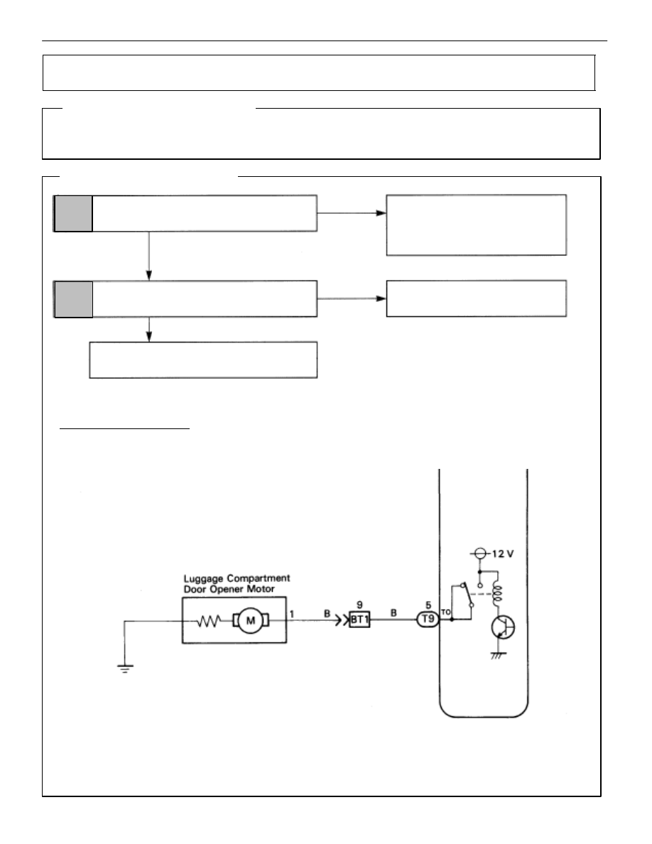
WIRING DIAGRAM

Luggage Compartment Door Opener Motor Circuit

      CIRCUIT DESCRIPTION

This circuit unlocks the luggage compartment door when the ECU sends signals to the luggage 
compartment door opener motor.

      DIAGNOSTIC CHART

BE–382

BODY ELECTRICAL SYSTEM

Door Lock Control System

OK

NG

OK

NG

INSPECTION PROCEDURE

1

Check voltage between terminal 1 of luggage compartment door opener motor and body
ground.

C

OK

P

1.

Remove luggage compartment trim rear cover.

2.

Disconnect the opener motor connector.

Measure voltage between terminal 1 of luggage
compartment door opener motor and body ground,
when opener switch is pulled and not pulled.

Check harness and connectors between ECU and lug-
gage compartmtne door opener motor (See page 

IN–27

).

2

Check luggage compartment door opener motor.

C

OK

Hint

Connect positive 


 lead to the opener motor connector

and negative 

lead to the body of the opener motor.

Operated motor shaft and gear.

Perform inspection in a short time (within 1 second).

Replace luggage compartment door opener motor.

Proceed to next circuit inpsection shown on ma-
trix chart (Seepage 

BE–371

).

BODY ELECTRICAL SYSTEM

Door Lock Control System

BE–383

Door Lock Control Switch Circuit

CIRCUIT DESCRIPTION

When the door lock control switch is pushed to the lock side, Lock terminal of the switch is grounded,
and when the switch is pushed to the unlock side, Unlock terminal is grounded (See wiring diagram
below).

WIRING DIAGRAM

NG

Check voltage between terminals 2 (3), 1(1)
of door lock control switch connector and
body ground.

OK

NG

OK

Check door lock control switch.

Check harness and connectors between ECU
and door lock control switch, switch and body
ground (See page 

IN–27

).

Replace door lock control switch.

1

2

Proceed to next circuit inspection
shown on matrix chart (See page

BE–371

).

Check and replace ECU

Repair or replace harness or
connector.

3

OK

NG

DIAGNOSTIC CHART

BE–384

BODY ELECTRICAL SYSTEM

Door Lock Control System

NG

OK

OK

NG

OK

NG

*1:  malfunction of the ECU can be considered possible

only when the problem symptom is the following:


Lock and/or unlock using the Door Lock Con-

trol Switch cannot be   done, neither on the driv-

er’s side nor on the passenger’s side.

INSPECTION PROCEDURE

1

Check voltage between terminals 2(3), 1(1) of door lock control switch connector and body
ground.

C

OK

Hint

P

Remove the door trim and service hole cover.

1.

Turn ignition switch ON.

2.

Measure voltage between terminals 2(3), 1(1) of
door lock control switch connector and body
ground, when door lock control switch is pressed to
the lock side, unlock side and not pressed.

The terminal number without brackets is for the LH, the
number with brackets is for the RH.

Proceed to next circuit inspection shown on matrix chart
(See page 

BE–371

).

2

Check door lock control switch.

C

OK

Hint

P

Disconnect the door lock control switch connector.

Check continuity between terminals 2(3), 1(1), and 8(2)
of door lock control switch connector, when door lock
control switch is pressed to the lock side, and unlock
side and not pressed.

The terminal number without brackets is for the LH, the
number with brackets is for the RH.

Replace door lock control switch.

3

Check harness and connectors between ECU and door lock control switch, switch and body
ground (See page 

IN–27

).

Repair or replace harness or connector.

Check and replace ECU. *1

BODY ELECTRICAL SYSTEM

Door Lock Control System

BE–385


Content   ..  186  187  188  189   ..