Lexus SC300 / Lexus SC400. Manual - part 173
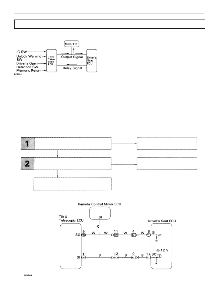
WIRING DIAGRAM
Check harness and connector between
ECU and tilt & telescopic ECU (See page
).
NG
NG
OK
OK
Check return operation of tilt and
telescopic ECU, and mirror ECU.
Repair or replace harness or
connector.
Check and replace tilt &
telescopic ECU.
Proceed to next circuit inspection shown on
matrix chart (See page
).
Serial Communication Circuit
CIRCUIT DESCRIPTION
Memory and return command signals and mutual commu-
nication during return operation pass between the ECU and
the tilt & telescopic ECU in the from of serial data communica-
tion. Signals activating memory and return operation are sent
from the tilt & telescopic ECU to the ECU and mirror ECU.
When the ECU receives a memory signals, its position is
memorized, and when a return signal is received, the position
is returned to the memorized position.
During return operation, tilt & telescopic ECU and ECU continue mutual communication constantly, and if a mal-
function should occur in the communication wire, the tilt & telescopic ECU stops signal output to the ECU and
stops return operation. However, the tilt & telescopic ECU continues return operation. Even with power return
stopped, manual switch operation of the power seat is possible. The mirror ECU receives activation signals only
and is not involved in reciprocal communication during return operation, so even when a reply signal from the
ECU to the tilt & telescopic ECU is abnormal and the power seat stops return operation, the mirror ECU contin-
ues return operation.
DIAGNOSTIC CHART
DIAGNOSTIC CHART
BE–306
–
BODY ELECTRICAL SYSTEM
Power Seat Control System (Driver’s Seat)