Lexus SC300 / Lexus SC400. Manual - part 169
 

  Index      Lexus     Lexus SC300 / Lexus SC400 - service repair manual


Search            


Content   ..  167  168  169  170   ..


Lexus SC300 / Lexus SC400. Manual - part 169


INSPECTION PROCEDURE

1

Check Motor

Slide

Front vertical

Rear vertical

OK

P

OK

OK

C

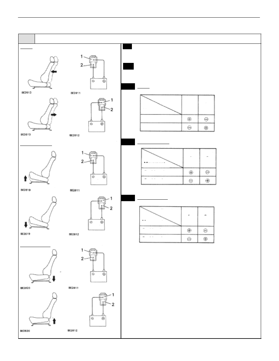
(1) Remove seat.

(2) Disconnect each motor connector.

Check seat movement when battery voltage is applied
to each motor.

Slide

Front vertical

Rear vertical

Terminal

Terminal

Terminal

Movement

Movement

Movement

Cushion rises

Forward

Back

Cushion lowers

Cushion rises

Cushion lowers

1

2

2

2

1

1

BODY ELECTRICAL SYSTEM

Power Seat Control System (Driver’s Seat)

BE–289

OK

NG

OK

NG

Reclining

OK

Reclining

Replace motor.

2

Check for open and short in harness and connector between ECU and motor (See page 

IN–27

).

Repair or replace harness or connector.

Proceed to next circuit inspection shown on 

matrix chart (See page 

BE–276

).

BE–290

BODY ELECTRICAL SYSTEM

Power Seat Control System (Driver’s Seat)

WIRING DIAGRAM

Position Sensor Power Source Circuit

CIRCUIT DESCRIPTION

This circuit provides power to the slide, front vertical, rear vertical and reclining sensors.

DIAGNOSTIC CHART

DIAGNOSTIC CHART

Check voltage between terminals PVCC
of ECU connector and body ground.

OK

Proceed to next circuit inspection
shown on matrix chart (See page

BE–276

).

NG

NG

OK

Check harness and connector connected to

terminal PVCC of ECU (See page 

IN–27

).

Repair or replace harness or
connector.

Check and replace ECU.

BE–292

BODY ELECTRICAL SYSTEM

Power Seat Control System (Driver’s Seat)

NG

OK

OK

NG

INSPECTION PROCEDURE

1

 Check voltage between terminal PVCC of ECU connector and body ground.

C

OK

P

Remove ECU with connectors still connected.

While operating the manual switch and moving the seat,
check voltage between terminal PVCC of ECU connec-
tor and body ground.

Voltage:

7 – 9 V

Proceed to next circuit inspection shown on matrix chart
(See page 

BE–276

).

2

Check for open and short in harness and connector connected to terminal PVCC of ECU (See

page 

IN–27

).

Check for open or short in the har-
nesses or connectors for the position
sensor power source circuit outlined
in the diagram with a thick line ( 

).

Repair or replace harness or connector.

Check and replace ECU.

BODY ELECTRICAL SYSTEM

Power Seat Control System (Driver’s Seat)

BE–293


Content   ..  167  168  169  170   ..