Lexus SC300 / Lexus SC400. Manual - part 144
2.
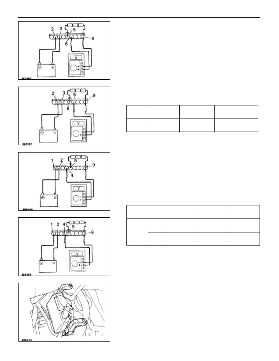
INSPECT MIRROR POSITION SENSORS
HINT: Strip off the vinyl tape of the connector and remove ter-
minals 1, 2, 3, 5 and 9 from the connector housing.
(a) Connect a series of three 1.5 volt dry cell batteries.
(b) Connect the positive (+) lead from the dry cell batteries
to terminal 5 and the negative (–) lead to terminal 9.
(c) Connect the positive (+) lead from the voltmeter to
terminal 6 and the negative (–) lead to terminal 9.
(d) Apply battery voltage to terminals 2 and 3, check that
the voltage gradually changes according to the table
below while the mirror moves between the uppermost
position and lowermost position.
Mirror
position
Lowermost
Uppermost
Voltage
2.8 – 5.0
Changes
gradually
0 – 0.9
If voltage value is not as specified, replace the motor assem-
bly.
(e) Disconnect the four leads of the battery and voltmeter.
(f) Connect the positive (+) lead from the voltmeter to
terminal 4 and the negative (–) lead to terminal 9.
(g) Apply battery voltage to terminals 1 and 2n inspect that
the voltage gradually changes according to the table
below while the mirror moves between the leftmost
position and rightmost position.
Mirror
Position
Leftmost
Rightmost
Voltage
Left
Mirror
2.8 – 5.0
Changes
gradually
0 – 0.9
Voltage
Right
Mirror
0 – 0.9
Changes
gradually
2.8 – 5.0
If voltage value is not as specified, replace the motor assem-
bly.
(Mirror ECU)
REMOVAL AND INSTALLATION OF
MIRROR ECU
REMOVAL AND INSTALL MIRROR ECU
(a) Remove the No. 1 under cover .
(See page
(b) Remove the two screws and disconnect the two
connectors and then pull out the ECU.
(c) For installation, follow the removal procedure in reverse.
–
BODY ELECTRICAL SYSTEM
Power Mirror Control System
BE–187