Lexus SC300 / Lexus SC400. Manual - part 98
 

  Index      Lexus     Lexus SC300 / Lexus SC400 - service repair manual


Search            


Content   ..  96  97  98  99   ..


Lexus SC300 / Lexus SC400. Manual - part 98


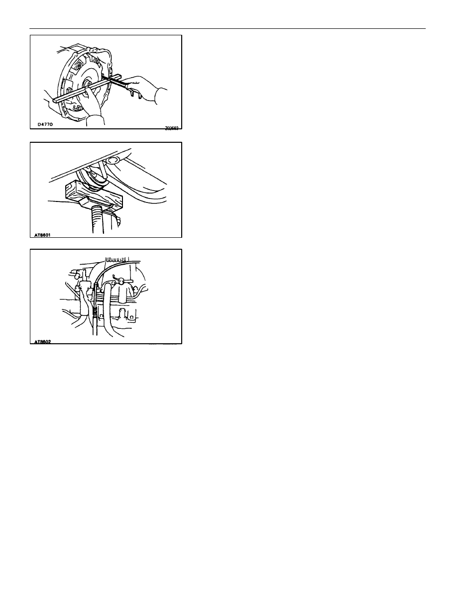
INSTALLATION MAIN POINTS

AT00L–01

1. 

CHECK TORQUE CONVERTER CLUTCH INSTALLATION
Using calipers and a straight edge, measure from the
installed surface of the torque converter clutch to the front
surface of the transmission housing.

Correct distance:

17.1 mm (0.673 in.)

If the distance is less than the standard, check for an improp-
er installation.

2. 

LIFT ENGINE FRONT SIDE

3. 

INSTALL THROTTLE CABLE

4. 

ADJUST THROTTLE CABLE
(See page 
AT–48)

5.  FILL TRANSMISSION WITH ATF AND CHECK FLUID

LEVEL
(See page 
AT–47)

NOTICE: Do not overfill.

Fluid type:

ATF Type T–II or equivalent

6. 

INSTALL PROPELLER SHAFT
(See page 
PR–12 to PR–14)

7. 

INSTALL EXHAUST PIPE
(See page  
EG–204)

AT–26

A304E (1UZ–FE) AUTOMATIC TRANSMISSION

ASSEMBLY REMOVAL AND INSTALLATION

SHIFT LOCK SYSTEM

COMPONENT AND CIRCUIT

AT0GL–02

A304E (1UZ–FE) AUTOMATIC TRANSMISSION

SHIFT LOCK SYSTEM

AT–27

ELECTRONIC CONTROL COMPONENTS
INSPECTION

AT0GM–02

1. 

INSPECT SHIFT LOCK CONTROL ECM
Using a voltmeter, measure the voltage at each terminal.

ÑÑÑÑÑ

ÑÑÑÑÑ

Connector

ÑÑÑÑÑÑÑ

ÑÑÑÑÑÑÑ

Terminal

ÑÑÑÑÑÑÑÑÑÑÑÑÑÑÑÑÑÑÑÑÑ

ÑÑÑÑÑÑÑÑÑÑÑÑÑÑÑÑÑÑÑÑÑ

Measuring condition

ÑÑÑÑÑÑ

ÑÑÑÑÑÑ

Voltage (V)

ÑÑÑÑÑ

ÑÑÑÑÑ

ÑÑÑÑÑÑÑ

ÑÑÑÑÑÑÑ

ACC–E

ÑÑÑÑÑÑÑÑÑÑÑÑÑÑÑÑÑÑÑÑÑ

ÑÑÑÑÑÑÑÑÑÑÑÑÑÑÑÑÑÑÑÑÑ

IG SW ACC position

ÑÑÑÑÑÑ

ÑÑÑÑÑÑ

10–14

ÑÑÑÑÑ

ÑÑÑÑÑ

ÑÑÑÑÑ

ÑÑÑÑÑÑÑ

ÑÑÑÑÑÑÑ

ÑÑÑÑÑÑÑ

IG–E

ÑÑÑÑÑÑÑÑÑÑÑÑÑÑÑÑÑÑÑÑÑ

ÑÑÑÑÑÑÑÑÑÑÑÑÑÑÑÑÑÑÑÑÑ

ÑÑÑÑÑÑÑÑÑÑÑÑÑÑÑÑÑÑÑÑÑ

IG SW ON position

ÑÑÑÑÑÑ

ÑÑÑÑÑÑ

ÑÑÑÑÑÑ

10–14

ÑÑÑÑÑ

ÑÑÑÑÑ

A

ÑÑÑÑÑÑÑ

ÑÑÑÑÑÑÑ

STP–E

ÑÑÑÑÑÑÑÑÑÑÑÑÑÑÑÑÑÑÑÑÑ

ÑÑÑÑÑÑÑÑÑÑÑÑÑÑÑÑÑÑÑÑÑ

Depress brake pedal

ÑÑÑÑÑÑ

ÑÑÑÑÑÑ

10–14

ÑÑÑÑÑ

ÑÑÑÑÑ

A

ÑÑÑÑÑÑÑ

ÑÑÑÑÑÑÑ

ÑÑÑÑÑÑÑÑÑÑÑÑÑÑÑÑÑÑÑÑÑ

ÑÑÑÑÑÑÑÑÑÑÑÑÑÑÑÑÑÑÑÑÑ


 IG SW ACC position and P position

ÑÑÑÑÑÑ

ÑÑÑÑÑÑ

0

ÑÑÑÑÑ

ÑÑÑÑÑ

ÑÑÑÑÑÑÑ

ÑÑÑÑÑÑÑ

KLS–E

ÑÑÑÑÑÑÑÑÑÑÑÑÑÑÑÑÑÑÑÑÑ

ÑÑÑÑÑÑÑÑÑÑÑÑÑÑÑÑÑÑÑÑÑ


 R, N, D, 2, L, position

ÑÑÑÑÑÑ

ÑÑÑÑÑÑ

7.5–11

ÑÑÑÑÑ

ÑÑÑÑÑ

ÑÑÑÑÑÑÑ

ÑÑÑÑÑÑÑ

ÑÑÑÑÑÑÑÑÑÑÑÑÑÑÑÑÑÑÑÑÑ

ÑÑÑÑÑÑÑÑÑÑÑÑÑÑÑÑÑÑÑÑÑ


 R, N, D, 2, L position (after one second)

ÑÑÑÑÑÑ

ÑÑÑÑÑÑ

6–9.5

ÑÑÑÑÑ

ÑÑÑÑÑ

ÑÑÑÑÑÑÑ

ÑÑÑÑÑÑÑ

ÑÑÑÑÑÑÑÑÑÑÑÑÑÑÑÑÑÑÑÑÑ

ÑÑÑÑÑÑÑÑÑÑÑÑÑÑÑÑÑÑÑÑÑ


 IG SW ON position and P position

ÑÑÑÑÑÑ

ÑÑÑÑÑÑ

0

ÑÑÑÑÑ

ÑÑÑÑÑ

B

ÑÑÑÑÑÑÑ

ÑÑÑÑÑÑÑ

SLS


– SLS


ÑÑÑÑÑÑÑÑÑÑÑÑÑÑÑÑÑÑÑÑÑ

ÑÑÑÑÑÑÑÑÑÑÑÑÑÑÑÑÑÑÑÑÑ


 Depress brake pedal

ÑÑÑÑÑÑ

ÑÑÑÑÑÑ

8–13.5

ÑÑÑÑÑ

ÑÑÑÑÑ

B

ÑÑÑÑÑÑÑ

ÑÑÑÑÑÑÑ

SLS 


 – SLS 


ÑÑÑÑÑÑÑÑÑÑÑÑÑÑÑÑÑÑÑÑÑ

ÑÑÑÑÑÑÑÑÑÑÑÑÑÑÑÑÑÑÑÑÑ


 Depress brake pedal (after 20 seconds)

ÑÑÑÑÑÑ

ÑÑÑÑÑÑ

6–8.5

ÑÑÑÑÑ

ÑÑÑÑÑ

ÑÑÑÑÑ

ÑÑÑÑÑÑÑ

ÑÑÑÑÑÑÑ

ÑÑÑÑÑÑÑ

ÑÑÑÑÑÑÑÑÑÑÑÑÑÑÑÑÑÑÑÑÑ

ÑÑÑÑÑÑÑÑÑÑÑÑÑÑÑÑÑÑÑÑÑ

ÑÑÑÑÑÑÑÑÑÑÑÑÑÑÑÑÑÑÑÑÑ


 R, N, D, 2, L position

ÑÑÑÑÑÑ

ÑÑÑÑÑÑ

ÑÑÑÑÑÑ

0

ÑÑÑÑÑ

ÑÑÑÑÑ

ÑÑÑÑÑÑÑ

ÑÑÑÑÑÑÑ

P

1

P

ÑÑÑÑÑÑÑÑÑÑÑÑÑÑÑÑÑÑÑÑÑ

ÑÑÑÑÑÑÑÑÑÑÑÑÑÑÑÑÑÑÑÑÑ


 IG SW ON, P position and depress brake pedal

ÑÑÑÑÑÑ

ÑÑÑÑÑÑ

0

ÑÑÑÑÑ

ÑÑÑÑÑ

C

ÑÑÑÑÑÑÑ

ÑÑÑÑÑÑÑ

P

1–

P

ÑÑÑÑÑÑÑÑÑÑÑÑÑÑÑÑÑÑÑÑÑ

ÑÑÑÑÑÑÑÑÑÑÑÑÑÑÑÑÑÑÑÑÑ


 R, N, D, 2, L position

ÑÑÑÑÑÑ

ÑÑÑÑÑÑ

9–13.5

ÑÑÑÑÑ

ÑÑÑÑÑ

C

ÑÑÑÑÑÑÑ

ÑÑÑÑÑÑÑ

P

2

–P

ÑÑÑÑÑÑÑÑÑÑÑÑÑÑÑÑÑÑÑÑÑ

ÑÑÑÑÑÑÑÑÑÑÑÑÑÑÑÑÑÑÑÑÑ


 IG SW ACC position and P position

ÑÑÑÑÑÑ

ÑÑÑÑÑÑ

9–13.5

ÑÑÑÑÑ

ÑÑÑÑÑ

ÑÑÑÑÑÑÑ

ÑÑÑÑÑÑÑ

P

2

–P

ÑÑÑÑÑÑÑÑÑÑÑÑÑÑÑÑÑÑÑÑÑ

ÑÑÑÑÑÑÑÑÑÑÑÑÑÑÑÑÑÑÑÑÑ


 R, N, D, 2, L position

ÑÑÑÑÑÑ

ÑÑÑÑÑÑ

0

2. 

INSPECT SHIFT LOCK SOLENOID

(a)  Disconnect the solenoid connector.
(b)  Using an ohmmeter, measure the resistance between

terminals.

Standard resistance:

20–28 


If resistance value is not as specified, replace the solenoid.

(c)  Apply the battery positive voltage between terminals.

At this time, confirm that the solenoid operates.
If solenoid operation is not as specified, replace solenoid.

AT–28

A304E (1UZ–FE) AUTOMATIC TRANSMISSION

SHIFT LOCK SYSTEM

3. 

INSPECT KEY INTERLOCK SOLENOID

(a)  Disconnect the solenoid connector.
(b)  Using an ohmmeter, measure the resistance between

terminals 7 and 8.

Standard resistance:

12–17 


If resistance value is not as specified, replace the solenoid.

(c)  Touch the solenoid with your finger and check that solenoid

operation can be felt when battery positive voltage.
If solenoid operation is not as specified, replace the solenoid.

4. 

INSPECT SHIFT LOCK CONTROL SWITCH
Inspect that there is continuity between each terminal.

A304E (1UZ–FE) AUTOMATIC TRANSMISSION

SHIFT LOCK SYSTEM

AT–29


Content   ..  96  97  98  99   ..