Lexus SC300 / Lexus SC400. Manual - part 81
 

  Index      Lexus     Lexus SC300 / Lexus SC400 - service repair manual


Search            


Content   ..  79  80  81  82   ..


Lexus SC300 / Lexus SC400. Manual - part 81


OK

NG

OK

NG

INSPECTION PROCEDURE

1

Check operation of speedometer.

Drive the vehicle and check if the operation of the speedometer in the combination meter is normal.

The No. 1 vehicle speed sensor is operating normally if the speedometer display is normal.

C

Hint

Check speedometer circuit. See combination meter
troubleshooting on BE section.

2

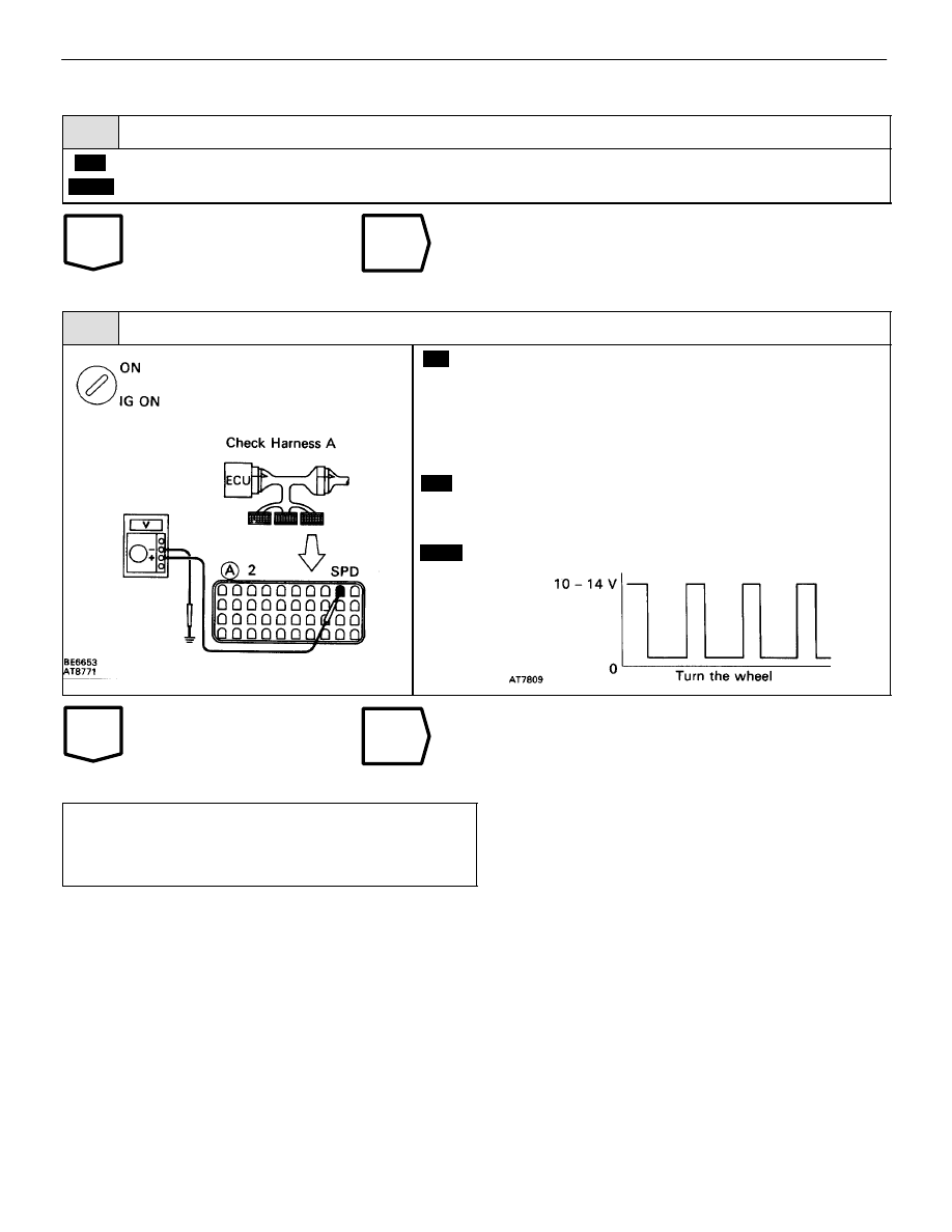
Check voltage between terminal SPD of ECM connector and body ground.

C

OK

P

3.

Connect the check harness A to the ECM
(See EG section.)

4.

Shift the shift lever to N position.

5.

Jack up one of the rear wheels.

6.

Turn ignition switch ON.

Measure voltage between terminal SPD of ECM con-
nector and body ground when he rear wheel is turned
slowly.

Voltage is generated intermittently.

Check speedometer circuit. See  combination meter
troubleshooting on BE section.

Proceed to next circuit inspection shown on ma-
trix chart (See page AT–66).
However, when diag. trouble code 42 is displayed,
check and replace ECM.

AT–80

A304E (1UZ–FE) AUTOMATIC TRANSMISSION

TROUBLESHOOTING

DTC

46

No. 4 Solenoid Valve Circuit (For Accumula-
tor Back Pressure Modulation)

CIRCUIT DESCRIPTION

The No. 4 solenoid valve controls the hydraulic pressure acting on the
brakes and clutches of the planetary gear units when gears are shifted and
performs smooth gear shifting.
The ECM determines optimum operating pressure according to the signals
from the throttle position sensor, vehicle speed sensor and O/D clutch
speed sensor and controls the volume of current flow to the solenoid valve.
The amount of electric current to the solenoid is controlled by the  (*) duty
ratio of ECM out put signals, causing momentary change to the hydraulic
pressure acting on the clutches during gear shifting.
When the duty ratio is high, the hydraulic pressure acting on the clutches
is low.
(*) Duty Ratio
The duty ration is the ration of the period of continuity in one cycle. For example, if A is the period of continuity
in one cycle, and B is the period of non–continuity, then

DTC No.

DTC Detecting Condition

Trouble Area

46

All conditions below are detected for 1 sec. or more.

2trip detection logic*

(a) ECM outputs duty signal to No. 4 solenoid in 90%

or higher duty ratio.

(b) Current to No. 4 solenoid:

330 


 100 Ma OR LESS

(O/D OFF indicator light doesn’t blink)


 No. 4 solenoid valve.


 Harness or connector between No. 4 sole-

noid valve and ECM


 ECM

*: See page AT–62.

Reference

Reference


Waveform between terminals SLN– and E

1

when engine is idling.


Waveform between terminals SLN– and E

1

 during shift

change.

AT–82

A304E (1UZ–FE) AUTOMATIC TRANSMISSION

TROUBLESHOOTING

AT–66

IN–33

WIRING DIAGRAM

DIAGNOSTIC CHART

DIAGNOSTIC CHART

A304E (1UZ–FE) AUTOMATIC TRANSMISSION

TROUBLESHOOTING

AT–83

OK

NG

INSPECTION PROCEDURE

1

Check No. 4 solenoid valve.

C

OK

P

C

OK

C

OK

C

OK

Check solenoid resistance

1.

Jack up the Vehicle

2.

Remove the oil pan.

3.

Disconnect the connector

Measure resistance between terminals 1 and 2 of sole-
noid connector.

Resistance:

5.1 – 5.5 


Check solenoid operation

Connect positive 


 lead with an 8–10 W bulb to terminal

1 of solenoid connector and negative 


 lead to terminal

2, then check the movement of the valve.

Reference

Check the solenoid’s operation

1.

Prepare a variable power supply.

2.

Connect positive 

lead of the variable power

supply to terminal 1 of solenoid connector and neg-
ative 


 lead to terminal 2.

3.

Check the movement of the valve when the voltage
is gradually increased. (A current greater than 1 A
should not be supplied.)

As the voltage is increased, the valve should move slow-
ly in the 

direction.

4.

Check the movement of the valve when the voltage
is cut off.

The valve should return in the 

direction.

Replace No. 4 solenoid valve.

Go to step 


.

AT–84

A304E (1UZ–FE) AUTOMATIC TRANSMISSION

TROUBLESHOOTING


Content   ..  79  80  81  82   ..