Lexus SC300 / Lexus SC400. Manual - part 3
 

  Index      Lexus     Lexus SC300 / Lexus SC400 - service repair manual


Search            


Content   ..  1  2  3  4  ..


Lexus SC300 / Lexus SC400. Manual - part 3


12.  Observe the following precautions to avoid damage to the

parts:

(a)  Do not open the cover or case of the ECU unless

absolutely necessary (If the IC terminals are touched, the

IC may be destroyed by static electricity.).

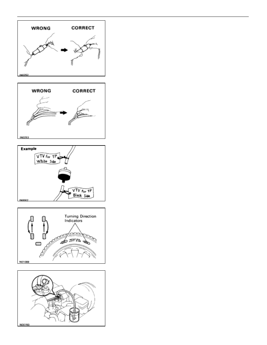
(b)  To pull apart electrical connectors, pull on the connector

itself, not the wires (See page 

BE–2

).

(c)  Be careful not to drop electrical components, such as

sensors or relays. It they are dropped on a hard floor,
they should be replaced and not reused.

(d)  When checking continuity at the wire connector, insert

the tester probe carefully to prevent terminals from
bending.

(e)  To disconnect vacuum hoses, pull on the end, not the

middle of the hose.

(f) 

When steam cleaning an engine, protect the distributor,
coil and air filter from water.

(g)  Never use an impact wrench to remove or install

temperature switches or temperature sensors.

(h)  When using a vacuum gauge, never force the hose onto

a connector that is too large. Use a step–down adapter
instead. Once the hose has been stretched, it may leak.

13.  Tag hoses before disconnecting them:

(a)  When disconnecting vacuum hoses, use tags to identify

how they should be reconnected.

(b)  After completing a job, double check that the vacuum

hoses are properly connected. A label under the hood
shows the proper layout.

14.  Installation of wheels

The wheel assemblies are of the uni–directional type and
must be rotated only between the front and rear as illustrated.
Wheels are marked with turning direction indicators.
When installing the wheels, check the marks carefully and
install the wheel correctly.

15.  Bleeding of traction control system

When repairing the brake master cylinder or TRAC system,
bleed the air out of the TRAC system (See page 

BR–7

).

CAUTION: Since the fluid is under high pressure, it could
spray out with great force, so be careful.

IN–6

INTRODUCTION

General Repair Instructions

TOTAL DIAGNOSTIC
COMMUNICATION LINK (TDCL)

The TDCL is provided inside the cabin (located under the left side
instrument panel) as a connector exclusively for diagnosis of data
from the engine, ECT, ABS, A/C, Airbag and Cruise Control Sys-
tem to improve serviceability. The check connector inside the en-
gine compartment is used for engine adjustment.

Connecting the following terminals of the TDCL to terminal E1 se-
lects the diagnosis mode shown.
NOTICE: Never make a mistake with the terminal connection
position as this will cause a malfunction.

Terminal

System

T

E1

Engine and ECT (Normal mode)

T

E2

 and T

E1

Engine and ECT (Test mode)

T

c

ABS, A/C, Airbag, Traction Control and Cruise
Control System

T

T

ECT

Refer to the respective system for the inspection method.
HINT: By connecting the TDCL up to a monitor specifically de-
signed for use with the TDCL, the diagnosis result for each system
can be read easily.

INTRODUCTION

Total Diagnostic Communication Link (TDCL)

IN–7

PRECAUTIONS FOR VEHICLES
EQUIPPED WITH SRS AIRBAG

The LEXUS SC400 is equipped with an SRS (Supplemental Re-

straint System) airbag.

Failure to carry out service operations in the correct sequence

could cause the airbag system to unexpectedly deploy during serv-

icing, possibly leading to a serious accident.

Further, if a mistake is made in servicing the airbag system, it is pos-

sible the airbag may fail to operate when required.

Before performing servicing (including removal or installation of

parts, inspection or replacement), be sure to read the following

items carefully, then follow the correct procedure described in this

manual.

Locations of Airbag Components

1. 

Malfunction symptoms of the airbag system are difficult to confirm,

so the diagnostic codes become the most important source of

information when troubleshooting.

When troubleshooting the airbag system, always inspect the diag-

nostic codes before disconnecting the battery. (See page 

AB–25

)

2. 

Work must be started after approx. 20 seconds or longer from

the time the ignition switch is turned to the LOCK position and

the negative (–) terminal cable is disconnected from the

battery.

(The airbag system is equipped with a back–up power source

so that if work is started within 20 seconds of disconnecting

the negative (–) terminal cable of the battery, the airbag may be

deployed.)

IN–8

INTRODUCTION

Precautions for Vehicles Equipped with SRS Airbag

When the negative (–) terminal cable is disconnected from
the battery, memory of the clock and audio systems will be
cancelled. So before starting work, make a record of the con-
tents memorized by each memory system. Then when work
is finished, reset the clock and audio systems as before.
When the vehicle has power tilt and power telescopic steer-
ing, power seat, power outside rear view mirror and power
shoulder belt anchorage, which are all equipped with
memory function, it is not possible to make a record of the
memory contents. So when the operation is finished, it will be
necessary to explain this fact to the customer, and ask the
customer to adjust the features and reset the memory.
To avoid erasing the memory of each memory system, never
use a back–up power supply from outside the vehicle.

3. 

Even in cases of a minor collision where the airbag does not
deploy, the front airbag sensors and the steering wheel pad
should be inspected. (See page 

AB–9

)

4. 

Never use airbag parts from another vehicle. When replacing
parts, replace them with new parts.

5. Before 

repairs, remove the airbag sensors if shocks are likely

to be applied to the sensors during repairs.

6. 

The center airbag sensor assembly contains mercury. After
performing replacement, do not destroy the old part. When
scrapping the vehicle or replacing the center airbag sensor
assembly itself, remove the center airbag sensor assembly
and dispose of it as toxic waste.

7.  Never disassemble and repair the front airbag sensors,

center airbag sensor assembly or steering wheel pad in order
to reuse it.

8. 

If the front airbag sensors, center airbag sensor assembly or
steering wheel pad have been dropped, or if there are cracks,
dents or other defects in the case, bracket or connector,
replace them with new ones.

9. 

Do not expose the front airbag sensors, center airbag sensor
assembly or steering wheel pad directly to hot air or flames.

10.  Use a volt/ohmmeter with high impedance (10 k

/V

minimum) for troubleshooting of the electrical circuit.

11.  Information labels are attached to the periphery of the airbag

components. Follow the notices.

12.  After work on the airbag system is completed, perform the

airbag warning light check (See page 

AB–30

).

INTRODUCTION

Precautions for Vehicles Equipped with SRS Airbag

IN–9


Content   ..  1  2  3  4  ..