Lexus ES300 (2002 year). Manual - part 385
 

  Index      Lexus     Lexus ES300 - service repair manual 2002 year


Search            


Content   ..  383  384  385  386   ..


Lexus ES300 (2002 year). Manual - part 385


A53763

IGF

E2

A54406

E10

IGT1

E2

+B

IGF IGT GND

A50294

05-146

-

DIAGNOSTICS

SFI SYSTEM (1MZ-FE)

299

2002 LEXUS ES300 REPAIR MANUAL   (RM911U)

3

INSPECT ECM

(a)

Disconnect the ignition coil connector.

(b)

Turn the ignition switch ON

(c)

Measure voltage between the terminals IGF and E2 of the
ECM connector.
Voltage: 4.5 - 5.5 V

OK

CHECK AND REPLACE ECM

NG

CHECK AND REPLACE ECM

4

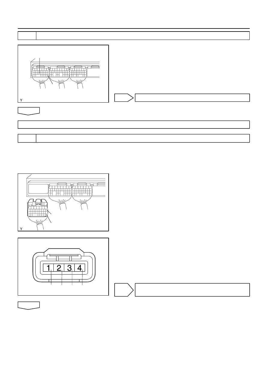
CHECK HARNESS AND CONNECTOR(ECM - IGNITION COIL)

HINT:
The procedure below is for No.1 cylinder. If a malfunction is
found on the other cylinders, check the circuit for the cylinder
with referring to this procedure.
(a)

Disconnect the ignition coil connector.

(b)

Disconnect the ECM E10 connector.

(c)

Check for open between the terminals IGT1 of the ECM
connector and IGT of the ignition coil connector.
Resistance: 1 

 or less

(d)

Check for short between the terminals IGT1 and E2 of the
ECM connector.
Resistance: 1 M

 or less

NG

REPAIR OR REPLACE HARNESS AND
CONNECTOR

OK

A53763

IGT1

E2

IGT2

IGT3

IGT4

IGT5

IGT6

A31764

A53763

IGT1

E2

IGT2

IGT3

IGT4

IGT5

IGT6

+B

IGF IGT GND

A50294

-

DIAGNOSTICS

SFI SYSTEM (1MZ-FE)

05-147

300

2002 LEXUS ES300 REPAIR MANUAL   (RM911U)

5

INSPECT ECM

(a)

Turn the ignition switch ON.

(b)

Measure the voltage between terminals IGT1 - IGT6 and
E2 of the ECM connector when the engine is cranked.
Voltage: More than 0.1 V and less than 4.5 V

HINT:
During cranking or idling, check the waveform between termi-
nals IGT1 - IGT6 and E2 of the ECM connector.

Item

Contents

Terminal

CH1: IGT1, IGT2, IGT3, IGT4, IGT5, IGT6 - E2
CH2: IGF - E2

Equipment Set

2V/DIV, 20ms/DIV

Condition

While the engine is cranking or idling

HINT:
Correct waveform appears as shown, with rectangle waves.

NG

CHECK AND REPLACE ECM

OK

6

INSPECT ECM

(a)

Disconnect the ignition coil with the igniter connector.

(b)

Turn the ignition switch ON.

(c)

Measure the voltage between terminals IGT1 - IGT6 and
E2 of the ECM connector when the engine is cranked.
Voltage: More than 0.1 V and less than 4.5 V

NG

CHECK AND REPLACE ECM

OK

7

CHECK IGNITION COIL ASSY(POWER SOUSE CIRCUIT)

(a)

Disconnect the ignition coil with the igniter connector.

(b)

Turn the ignition switch ON.

(c)

Measure voltage between terminals+B and GND of the
ignition coil with the igniter connector.
Voltage: 9 - 14 V

+B

IGF IGT GND

A50294

1

5

6

2

3

7

8

4

A56879

IG2

05-148

-

DIAGNOSTICS

SFI SYSTEM (1MZ-FE)

301

2002 LEXUS ES300 REPAIR MANUAL   (RM911U)

NG

REPAIR OR REPLACE POWER SOURCE

OK

8

CHECK HARNESS AND CONNECTOR(IGUNITION SWITCH - IGNITION COIL)

(a)

Disconnect the ignition coil with the igniter connector.

(b)

Disconnect the ignition switch connector.

(c)

Check open between the terminals +B of the ignitioncoil
with igniter connector and IG2 of the ignition switch.
Resistance: 1 

 or less

NG

REPAIR OR REPLACE HARNESS AND
CONNECTOR

OK

REPLACE IGNITION COIL ASSY

051MZ-08

05-18

-

DIAGNOSTICS

SFI SYSTEM (1MZ-FE)

171

2002 LEXUS ES300 REPAIR MANUAL   (RM911U)

DIAGNOSTIC TROUBLE CODE CHART

Parameters listed in the chart may not be exactly the same as your reading due to the type of instrument
or other factors.
If a malfunction code is displayed during the DTC check in check mode, check the circuit for the codes listed
in the table below. For details of each code, turn to the page referred to under the ’’See page ’’ for the respec-
tive ’’DTC No.’’ in the DTC chart.
SAE CONTROLLED

DTC No.

(See Page)

Detection Item

Trouble Area

MIL

*1

Memory

P0100

(

05-31

)

Mass Air Flow Circuit Malfunc-
tion


Open or short in intake air flow meter circuit


Intake air flow meter


ECM


P0101

(

05-37

)

Mass Air Flow Circuit Range/
Performance Problem


Intake air flow meter


P0110

(

05-38

)

Intake Air Temp. Circuit Malfunc-
tion


Open or short in intake air temp. sensor circuit


Intake air temp. sensor (inside intake air flow meter)


ECM


P0115

(

05-41

)

Engine Coolant Temp. Circuit
Malfunction


Open or short in E.F.I. engine coolant temp. sensor circuit


E.F.I. engine coolant temp. sensor


ECM


P0116

(

05-44

)

Engine Coolant Temp. Circuit
Range/Performance Problem


Cooling system


E.F.I. engine coolant temp. sensor


P0120

(

05-45

)

Throttle/Pedal Position Sensor/
Switch ”A” Circuit Malfunction


Open or short in throttle position sensor circuit


Throttle position sensor


ECM


P0121

(

05-51

)

Throttle/Pedal Position Sensor/
Switch ”A” Circuit Range/Perfor-
mance Problem


Throttle body assy (Throttle position sensor)


ECM


P0125

(

05-52

)

Insufficient Coolant Temp. for
Closed Loop Fuel Control


Open or short in A/F sensor (bank 1, 2 sensor 1) circuit


A/F sensor (bank 1, 2 sensor 1)


Air induction system


Fuel pressure


Injector


Gas leakage on exhaust system


PCV hose connection


ECM


P0128

(

05-58

)

Thermostat Malfunction


Thermostat


Cooling system


E.F.I. engine coolant temp. sensor


ECM


P0136

(

05-59

)

Heated Oxygen Sensor Circuit
Malfunction (Bank 1 Sensor 2)


Open or short in heated oxygen sensor circuit


Oxygen sensor


P0141

(

05-63

)

Heated Oxygen Sensor Circuit
Malfunction (Bank 1 Sensor 2)


Open or short in heater circuit of heated oxygen sensor


Oxygen sensor heater


ECM


P0156

(

05-59

)

Heated Oxygen Sensor Circuit
Malfunction (Bank 2 Sensor 2)


Same as DTC No. P0136


P0161

(

05-63

)

Heated Oxygen Sensor Circuit
Malfunction (Bank 2 Sensor 2)


Same as DTC No. P0141


Content   ..  383  384  385  386   ..