Lexus ES300 (2002 year). Manual - part 305
 

  Index      Lexus     Lexus ES300 - service repair manual 2002 year


Search            


Content   ..  303  304  305  306   ..


Lexus ES300 (2002 year). Manual - part 305


F40456

NEO

F03007

(Reference)

3 - 6 V

Below 1 V

-

DIAGNOSTICS

ABS WITH EBD & BA & TRAC & VSC SYSTEM

05-341

494

2002 LEXUS ES300 REPAIR MANUAL   (RM911U)

2

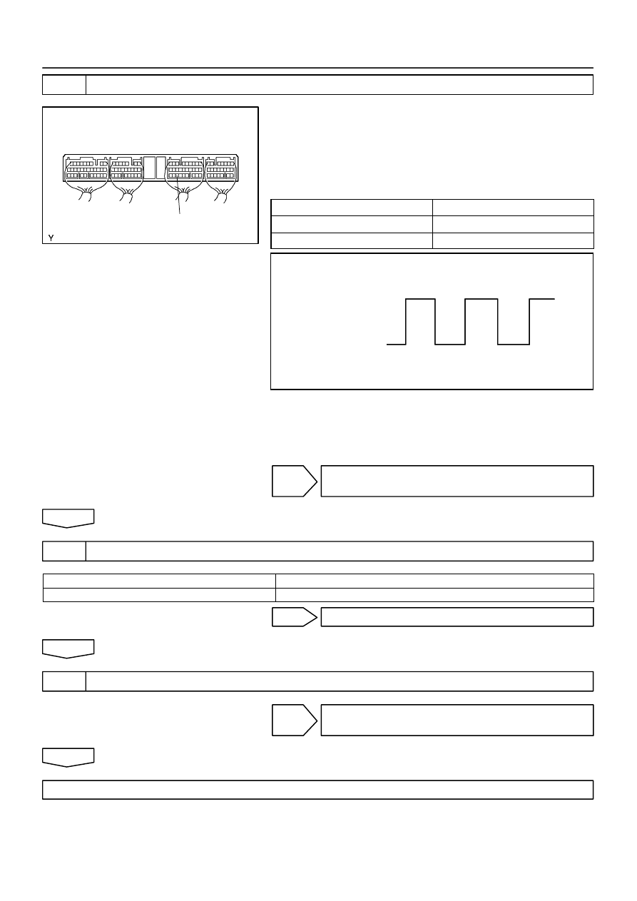
CHECK SKID CONTROL ECU TERMINAL VOLTAGE(NEO TERMINAL)

(a)

Remove skid control ECU with connectors still con-
nected.

(b)

Turn ignition switch ON.

(c)

Measure voltage between terminal NEO of skid control
ECU and body ground for the engine conditions below.
OK:

Engine condition

Voltage

OFF (IG ON)

3 - 6 V or below 1 V

ON (Idling)

3 - 6 V 

 below 1 V (Pulse)

NG

CHECK AND REPLACE ECM AND SKID
CONTROL ECU

OK

3

RECONFIRM DTC(See page 

05-288

)

A

Malfunction Code

B

Normal Code

B

END

A

4

CHECK CONTACT CONDITION(EACH CONNECTION)

NG

CHECK AND REPAIR HARNESS AND
CONNECTOR

OK

CHECK AND REPLACE ECM AND SKID CONTROL ECU

055XI-02

05-246

-

DIAGNOSTICS

ABS WITH EBD SYSTEM

399

2002 LEXUS ES300 REPAIR MANUAL   (RM911U)

DIAGNOSTIC TROUBLE CODE CHART

HINT:


Using SST 09843-18040, connect the terminals Tc and CG of the DLC3.


If any abnormalities are not found when inspecting the parts, inspect the ECU and wire harness.


If a malfunction code is displayed during the DTC check, check the circuit listed in the code. For details
of each code, refer to the ”See page” under the respective ”DTC No.” in the following DTC chart.

DTC No.

(See Page)

Detection Item

Trouble Area

C0278/11

(

05-263

)

Open circuit in ABS solenoid relay circuit


Fusible link block


ABS No. 2 fuse

C0279/12

(

05-263

)

Short circuit in ABS solenoid relay circuit


ABS No. 2 fuse


ABS solenoid relay


ABS solenoid relay circuit

C0273/13

(

05-261

)

Open circuit in ABS motor relay circuit


Fusible link block


ABS No. 3 fuse

C0274/14

(

05-261

)

Short circuit in ABS motor relay circuit


ABS No. 3 fuse


ABS motor relay


ABS motor relay circuit

C0226/21

(

05-259

)

Open or short circuit in 2-position solenoid circuit for right front
wheel


Brake actuator


SFRR or SFRH circuit

C0236/22

(

05-259

)

Open or short circuit in 2-position solenoid circuit for left front
wheel


Brake actuator


SFLR or SFLH circuit

C0246/23

(

05-259

)

Open or short circuit in 2-position solenoid circuit for right rear
wheel


Brake actuator


SRRR or SRRH circuit

C0256/24

(

05-259

)

Open or short circuit in 2-position solenoid circuit for left rear
wheel


Brake actuator


SRLR or SRLH circuit

C0200/31

(

05-251

)

Right front wheel speed sensor signal malfunction


Right front, left front speed sensor


Speed sensor rotor

C0205/32

(

05-251

)

Left front wheel speed sensor signal malfunction


S eed sensor rotor


Speed sensor rotor installation


Each speed sensor circuit

C0210/33

(

05-255

)

Right rear wheel speed sensor signal malfunction


Speed sensor rotor installation


Right rear, left rear speed sensor

C0215/34

(

05-255

)

Left rear wheel speed sensor signal malfunction


Right rear, left rear s eed sensor


Speed sensor rotor


Each speed sensor circuit

C1235/35

(

05-251

)

Foreign matter is attached on the tip of the right front sensor


Right front or left front speed sensor

C1236/36

(

05-251

)

Foreign matter is attached on the tip of the left front sensor


Right front or left front s eed sensor


Speed sensor rotor

C1238/38

(

05-255

)

Foreign matter is attached on the tip of the right rear sensor


Right rear or left rear speed sensor

C1239/39

(

05-255

)

Foreign matter is attached on the tip of the left rear sensor


Right rear or left rear s eed sensor


Speed sensor rotor

C1241/41

(

05-265

)

Power source voltage down


Power source harness and connector


Battery


Charging system


Power source circuit

C1249/49

(

05-268

)

Open circuit in stop light switch circuit


Stop lamp switch harness and connector


Stop light bulb


Stop light switch circuit


Stop lamp switch

-

DIAGNOSTICS

ABS WITH EBD SYSTEM

05-247

400

2002 LEXUS ES300 REPAIR MANUAL   (RM911U)

C1251/51

(

05-270

)

Pump motor is locked

ABS pump motor

Always ON

(

05-272

)

Malfunction in ECU or power source voltage up


Battery


Charging system


Skid control ECU

HINT:
There is a case that hand-held tester cannot be used when the ABS warning light is always ON.

DTC of speed sensor check function:

DTC No.

Detection Item

Trouble Area

C1271/71

Low output voltage of right front speed sensor


Right front speed sensor


Sensor installation


Sensor rotor

C1272/72

Low output voltage of left front speed sensor


Left front speed sensor


Sensor installation


Sensor rotor

C1273/73

Low output voltage of right rear speed sensor


Right rear speed sensor


Sensor installation


Sensor rotor

C1274/74

Low output voltage of left rear speed sensor


Left rear speed sensor


Sensor installation


Sensor rotor

C1275/75

Abnormal change in output voltage of right front speed sensor

Right front speed sensor rotor

C1276/76

Abnormal change in output voltage of left front speed sensor

Left front speed sensor rotor

C1277/77

Abnormal change in output voltage of right rear speed sensor

Right rear speed sensor rotor

C1278/78

Abnormal change in output voltage of left rear speed sensor

Left rear speed sensor rotor

F41984

B-R

A5

SRC1

1E

GR-R

Skid Control ECU

ABS R/B

ABS SOL Relay

ABS No.3

W

3

5

1

2

2

2

2

2

2

1

1A

1

1

1

1

2

AL

T

W-L

A5

A5

A5

A5

A5

A5

A5

A5

S5

4

S5

5

S5

2

S5

3

S8

21

S8

4

S8

5

S8

31

S8

10

S8

1

B-Y

Y-R

Y-B

L-R

Y-G

B-W

B-L

20

10

19

9

26

34

27

28

23

GR

BS

SRC2

SRM1

SRM2

SM1+

SM1-

SM2+

SM2-

Battery

FL 
MAIN

B-G

SRC1

SRC2

SRM1

SRM2

SM1+

SM1-

SM2+

SM2-

R+

SR

7

ABS & Traction
Actuator

Engine Room J/B

Engine 
Room R/B

B-G

05-342

-

DIAGNOSTICS

ABS WITH EBD & BA & TRAC & VSC SYSTEM

495

2002 LEXUS ES300 REPAIR MANUAL   (RM911U)

DTC

C1225/25 SMC SOLENOID CIRCUIT

DTC

C1226/26 SRM SOLENOID CIRCUIT

DTC

C1227/27 SRC SOLENOID CIRCUIT

CIRCUIT DESCRIPTION

This solenoid goes on when signals are received from the ECU and controls the pressure acting on the wheel
cylinders thus controlling the braking force.

DTC No.

DTC Detecting Condition

Trouble Area

C1225/25

Open or short circuit for SM1 or SM2 circuit continues for

0.05 sec. or more.


Brake actuator


SM1 or SM2 circuit

C1226/26

Open or short circuit for SRM1 or SRM2 circuit continues

for 0.05 sec. or more.


Brake actuator


SRM1 or SRM2 circuit

C1227/27

Open or short circuit for SRC1 or SRC2 circuit continues

for 0.05 sec. or more.


Brake actuator


SRC1 or SRC2 circuit

WIRING DIAGRAM

055VZ-02


Content   ..  303  304  305  306   ..