Lexus ES300 (2002 year). Manual - part 124
 

  Index      Lexus     Lexus ES300 - service repair manual 2002 year


Search            


Content   ..  122  123  124  125   ..


Lexus ES300 (2002 year). Manual - part 124


CHASSIS – U150E AUTOMATIC TRANSAXLE

CH-25

199CH06

5th

3rd

4th

3rd

5th 4th

5th

(Brake Operating)

5th

3rd

4th

3rd

4th

5th

without Control

with Control

Brake Operating

162CH10

Smaller

Uphill

Referencce acceleration

Actual acceleration

Greater

Downhill

Actual Acceleration < Reference Acceleration

Actual Acceleration > Reference Acceleration

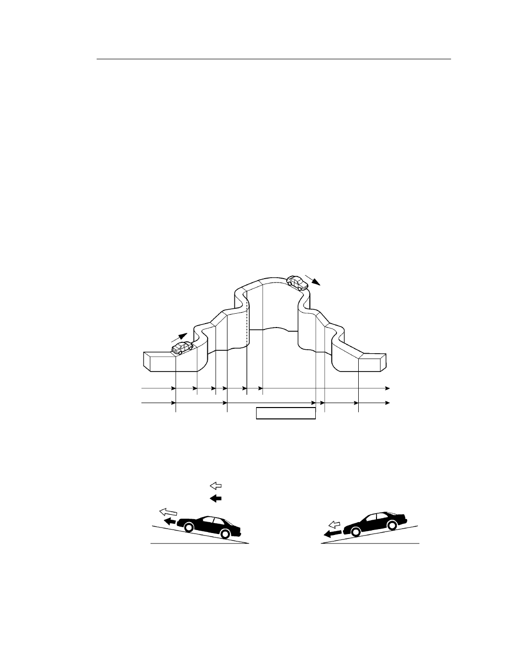
6. Shifting Control in Uphill/Downhill Traveling

General

This control minimizes the shifting of gears when the driver operates the accelerator pedal while driving
on a winding road with ups and downs, in order to ensure a smooth drive.

Shift control in uphill traveling

When the ECM determines uphill travel before the transaxle attempts to shift up into 5th or after it has
shifted down into 4th, it prohibits the transaxle from shifting up into 5th.
When the ECM determines uphill travel with a steeper grade, it automatically shifts down into 3rd and thus
prevents the transaxle from shifting up into 4th.

Shift control in downhill traveling

When the ECM determines downhill travel, it shifts down the transaxle from 5th to 4th in accordance with
the brake operation signal that is input when the driver operates the brake pedal.
When the ECM determines downhill travel with a steeper grade, and a brake operation signal is input again,
the ECM shifts the transaxle down from 4th to 3rd.

Uphill / Downhill Judgment

The actual acceleration calculated from the speed sensor signal is compared with the reference acceleration
stored in the ECM to judge uphill or downhill traveling.

CHASSIS – U150E AUTOMATIC TRANSAXLE

CH-26

161ES26

Line Pressure

Primary Regulator

Pump

Fluid
Pressure

Current

Throttle Pressure

Solenoid Valve SLT

Solenoid Drive Signal

Trans-
axle

Engine

ECM

Input Turbine Speed Sensor

Fluid Temperature

Shift Position

Throttle Valve Opening

Intake Air Volume
Engine Coolant Temperature
Engine rpm

7. Line Pressure Optimal Control

Through the use of the solenoid valve SLT, the line pressure is optimally controlled in accordance with the
engine toque information, as well as with the internal operating conditions of the toque converter and the
transaxle.
Accordingly, the line pressure can be controlled minutely in accordance with the engine output, traveling
condition, and the ATF temperature, thus realizing smooth shift characteristics and optimizing the workload
in the oil pump.

CHASSIS – U150E AUTOMATIC TRANSAXLE

CH-27

211CH21

Service Tip

The length of time to clear the DTC by the battery terminal disconnection has been changed from the
previous 10 seconds to 1 minute.

8. Diagnosis

 When the ECM detected a malfunction, the

ECM makes a diagnosis and memorizes the
failed section.
Furthermore, the MIL (Malfunction Indicator
Lamp) in the combination meter illuminates or
blinks to inform the driver.

 At the same time, the DTCs (Diagnosis Trouble

Codes) are stored in memory. The DTCs can be
read by connecting a hand-held tester.

–Changes (from U140E)–

The DTCs (Diagnosis Trouble Codes) listed below have been added.

DTC No.

Detection Item

P0711

Transmission Fluid Temp. Sensor Malfunction
(Fluid Temp. Sensor)

P0760

Shift Solenoid C Malfunction
(Solenoid Valve SL3)

P0763

Shift Solenoid C Electrical Malfunction
(Solenoid Valve SL3)

P1815

Solenoid Valve SR Malfunction

P1818

Solenoid Valve SR Electrical Malfunction

CHASSIS – U150E AUTOMATIC TRANSAXLE

CH-28

9. Fail Safe

This function minimizes the loss of operability when any abnormality occurs in each sensor or solenoid.

 Fail-Safe Control List 


Malfunction Part

Function

Speed Sensor

During a speed sensor malfunction, the vehicle speed is detected through
the signals from the counter gear speed sensor to effect normal control.

Fluid Temp. Sensor

During a fluid temp. sensor malfunction, 5th upshift is prohibited.

Counter Gear Speed Sensor

During a counter gear speed sensor malfunction, 5th upshift is prohibited.

Solenoid Valve SL1,

The current to the failed solenoid valve is cut off and control is effected by
operating the other solenoid valves with normal operation.
Shift control is effected as described in the table below, depending on the

Solenoid Valve SL1,
SL2, SL3, and S4

Shift control is effected as described in the table below, depending on the
failed solenoid.
Even if starting the engine under this condition, the gear position remains
where it was before.

: ON : Lock-up ON x: OFF

SL1


x


x

x

Solenoid

SL2


Normal

Solenoid
Valve

SL3

x

x

x


S4

x

x

x

x


Gear Position

1st

2nd

3rd

4th

5th

SL1

SL1

x

SL1
Malfunction

Solenoid

SL2


Malfunction
(During

Solenoid
Valve

SL3

x

x

x

  x

  x

(

g

driving at 1st

2 d)

S4

x

x

x

x

  x

or 2nd)

Gear Position

1st 

 2nd

2nd

3rd 

 2nd 4th  2nd 5th  2nd

SL1

x

SL1
M lf

ti

Solenoid

SL2


Malfunction
(During

Solenoid
Valve

SL3

x

x

x

  x

  x

(During
driving at 3rd)

S4


driving at 3rd)

Gear Position

1st 

 4th

2nd 

 4th

3rd 

 4th

4th

5th 

 4th

SL1

SL1

x

SL1
Malfunction

Solenoid

SL2


Malfunction
(During

Solenoid
Valve

SL3


(

g

driving at 4th

5 h)

S4

x

x

x

x


or 5th)

Gear Position

1st 

 4th

2nd 

 4th

3rd 

 4th

4th

5th

(Continued)


Content   ..  122  123  124  125   ..