Lexus ES300 (1997 year). Manual - part 606
7
B
Q : Explains the system outline.
R : Indicates values or explain the function for reference during troubleshooting.
S : Indicates the reference page showing the position on the vehicle of the parts in the system circuit.
Example: Part “P 4” (Power Window Master SW) is on page 21 of the manual.
* The letter in the code is from the first letter of the part, and the number indicates its order in
parts starting with the letter.
Example: P 4
HINTS:
Part is 4th in order
Power Window Master SW
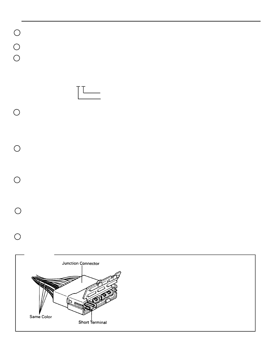
Junction connector (code: J1 to J19) in this manual
include a short terminal which is connected to a
number of wire harnesses. Always perform inspec-
tion with the short terminal installed. (When instal-
ling the wire harnesses, the harnesses can be con-
nected to any position within the short terminal
grouping. Accordingly, in other vehicles, the same
position in the short terminal may be connected to
a wire harness from a different part.)
Wire harness sharing the same short terminal
grouping have the same color.
T : Indicates the reference page showing the position on the vehicle of Relay Block Connectors in the system
circuit.
Example: Connector “1” is described on page 16 on this manual and is installed on the left side of the
instrument panel.
U : Indicates the reference page showing the position on the vehicle of J/B and Wire Harness in the system
circuit.
Example: Connector “3B”connects the Cowl Wire and J/B No. 3. It is described on page 14 of this manual,
and is installed on the instrument panel left side.
V : Indicates the reference page describing the wiring harness and wiring harness connector (the female wiring
harness is shown first, followed by the male wiring harness).
Example: Connector “ID1”connects the front door RH wire (female) and cowl wire (male). It is described
on page 26 of this manual, and is installed on the right side kick panel.
W : Indicates the reference page showing the position of the ground points on the vehicle.
Example: Ground point “IC” is described on page 24 of this manual and is installed on the cowl left side.
X : Indicates the reference page showing the position of the splice points on the vehicle.
Example: Splice point “I 5” is on the Cowl Wire Harness and is described on page 24 of this manual.