Lexus ES300 (1997 year). Manual - part 439
 

  Index      Lexus     Lexus ES300 - service repair manual 1997 year


Search            


Content   ..  437  438  439  440   ..


Lexus ES300 (1997 year). Manual - part 439


DI0D6–01

I00371

A13

A14

1

2

3

4

5

6

7

8

9

10

11

12

13

14

15

26

16

17

18

19

20

21

22

23

24

25

1

2

3

4

5

6

7

8

9

10

11

12

13

14

15

16

DIAGNOSTICS

AIR CONDITIONING SYSTEM

DI–533

685

1997 LEXUS ES300   (RM511U)

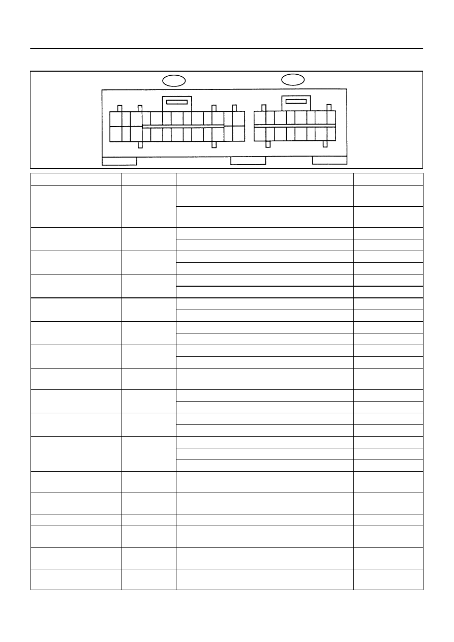
TERMINALS OF ECM

Symbols (Terminals No.)

Wiring Color

Condition

STD Voltage (V)

MGCR 

 GND 

L Y

W B

Start the engine and push AUTO switch.

A/C switch ON

Below 1 V

MGCR 

 GND 

(A14–2 

 A13–14)

L–Y 

 W–B

Start the engine and push AUTO switch.

A/C switch OFF

10 – 14 V

TAM

SG (A14 3

A13 1)

Y

W R

IG ON. Ambient Temp.: 25 

°

C (77 

°

F)

1.35 – 1.75 V

TAM 

 SG (A14–3 

 A13–1)

 W–R

IG ON. Ambient Temp.: 40 

°

C (104 

°

F)

0.85 – 1.25 V

TR

SG (A14 4

A13 1)

G Y

W R

IG ON. Room Temp.: 25 

°

C (77 

°

F)

1.8 – 2.2 V

TR 

 SG (A14–4 

A13–1)

G–Y 

 W–R

IG ON. Room Temp.: 40 

°

C (104 

°

F)

1.2 – 1.6 V

TS

SG (A14 5

A13 1)

W

W R

IG ON. Sensor subjected to electrical light.

1 V or more

TS 

 SG (A14–5 

 A13–1)

 W–R

IG ON. Sensor covered by cloth

Below 1 V

TE

SG (A14 6

A13 1)

L W

W R

IG ON. Evaporator Temp.: 0 

°

C (32 

°

F)

2.0 – 2.4 V

TE 

 SG (A14–6 

 A13–1)

L–W 

 W–R

IG ON. Evaporator Temp.: 15 

°

C (59 

°

F)

1.4 – 1.8 V

TPI

SG (A14 7

A13 1)

P L

W R

Push Recircu Switch

3.5 – 4.5 V

TPI 

 SG (A14–7 

 A13–1)

P–L 

 W–R

Push Fresh Switch

0.5 – 1.8 V

TP

SG (A14 8

A13 1)

B Y

W R

Set Temp.: Max. Cool

3.5 – 4.5 V

TP 

 SG (A14–8 

 A13–1)

B–Y 

 W–R

Set Temp.: Max. Hot

0.5 – 1.8 V

PSW 

 GND

(A14–9 

 A13–14)

L–B 

 W–B

IG ON.

Below 1 V

ACT 

 GND

LG R

W B

Start the Engine (Idling). Operate the Compressor

10 – 14 V

ACT 

 GND

(A14–10 

 A13–14)

LG–R 

 W–B

Start the Engine (Idling). Do not operate Compressor

Below 1.5 V

AC1 

 GND

B Y

W B

Start the engine. A/C Switch ON.

Below 1 V

AC1 

 GND

(A14–13 

 A13–14)

B–Y 

 W–B

Start the engine. A/C Switch OFF.

More than 1 V

Engine Coolant Temp.: 0 

°

C (32 

°

F)

2.8 – 3.8 V

TW2 

 SG (A14–14 

 A13–1)

 W–R

Engine Coolant Temp.: 40 

°

C (104 

°

F)

1.8 – 2.2 V

TW2 

 SG (A14 14 

 A13 1)

 W R

Engine Coolant Temp.: 70 

°

C (158 

°

F)

0.9 – 1.3 V

BLW 

 GND

 (A14–16 

 A13–14)

B–W 

 W–B

IG ON. Operate the Blower Motor

Below 1.5 V

SG 

 Body

(A13–1 

 Body Ground)

W–R 


Body Ground

Always

 or less

ILL 

 GND (A13–2 

 A13–14)

 W–B

Turn the Light Control Switch to TAIL position.

10 – 14 V

LOCK 

 GND 

(A13–3 

 A13–14)

W–L 

 W–B

IG OFF. at 20 

°

C (68 

°

F)

65 – 125 

FACE 

 GND

(A13–4 

 A13–14)

L–W 

 W–B

IG ON. Air Flow: FACE

Below 1 V

SECU 

 GND

(A13–5 

A13–14)

 W–B

IG ON.

Below 1 V

DI–534

DIAGNOSTICS

AIR CONDITIONING SYSTEM

686

1997 LEXUS ES300   (RM511U)

Symbols (Terminals No.)

Wiring Color

Condition

STD Voltage (V)

AIF 

 AIR (A13–6 

A13–7)

L–Y 

 R

IG ON.

13 – 19 

AMC 

 AMH

(A13–8 

 A13–9)

 G–R

IG ON.

13 – 19 

HR 

 GND

L W

W B

IG ON. Operate the Blower Motor

Below 1 V

HR 

 GND

(A13–10 

 A13–14)

L–W 

 W–B

IG ON. Do not operate the Blower Motor

10 – 14 V

S5 

 SG (A13–11 

 A13–1)

 W–R

IG ON.

4 – 6 V

S5

TS (A13 11

A14 5)

L

W

IG ON. Sensor Subjected to Electrical Light.

Below 4 V

S5 

 TS (A13–11 

A14–5)

 W

IG ON. Sensor Covered by a Cloth.

4 – 4.5 V

ILL+ 

 GND

(A13–12 

 A13–14)

 W–B

Turn the Light Control Switch to TAIL position.

10 – 14 V

B+ 

 GND

(A13–13 

 A13–14)

W–R 

 W–B

IG OFF.

10 – 14 V

GND 

Body Ground

(A13–14 

 Body Ground)

W–B 

Body Ground

Always

 or less

IGN 

 GND

(A13–16 

 A13–14)

B–O 

 W–B

Start the Engine

10 – 14 V

B/L 

 GND

(A13–17 

 A13–14)

 W–B

IG ON. Air Flow: BI–LEVEL.

Below 1 V

FOOT 

 GND

(A13–18 

 A13–14)

L–R 

 W–B

IG ON. Air Flow: FOOT.

Below 1 V

F/D 

 GND

(A13–19 

 A13–14)

B–L 

 W–B

IG ON. Air Flow: FOOT/DEF

Below 1 V

DEF 

 GND

(A13–20 

 A13–14)

L–O 

 W–B

IG ON. Air Flow: DEF

Below 1 V

RDFG 

 GND

L G

W B

Rear Defogger Switch ON.

Below 1 V

RDFG 

 GND

(A13–23 

 A13–14)

L–G 

 W–B

Rear Defogger Switch OFF

10 – 14 V

TELI 

 GND

(A13–24 

 A13–14)

L–R 

 W–B

IG ON. Hand Free Telephone ON.

Below 1 V

TC 

 GND

B R

W B

Light Control Switch Position: TAIL.

Rheostat Volume: Most Upward

10 – 14 V

TC 

 GND

(A13–25 

 A13–14)

B–R 

 W–B

Light Control Switch Position: TAIL.

Rheostat Volume: Most Downward

Below 1 V

IG+ 

 GND

(A13–16 

 A13–14)

L–B 

 W–B

IG ON.

10 – 14 V

DI0D7–01

DIAGNOSTICS

AIR CONDITIONING SYSTEM

DI–535

687

1997 LEXUS ES300   (RM511U)

PROBLEM SYMPTOMS TABLE

Symptom

Suspect Area

See page

Whole functions of the A/C system does not operate.

1. IG power source circuit

2. ECU (A/C control assembly)

DI–576

IN–27

Air Flow Control: No blower operation

1. Heater main relay circuit

2. Blower motor circuit

3. Engine coolant temperature sensor circuit

4. IG power source circuit

5. ECU (A/C control assembly)

DI–580

DI–583

DI–546

DI–576

IN–27

Air Flow Control: No blower control

1. Blower motor circuit

2. IG power source circuit

3. Heater main relay circuit

DI–583

DI–576

DI–580

Air Flow Control: Insufficient air out

Blower motor circuit

DI–583

Temperature Control: No cool air comes out

1. Volume of refrigerant

2. Drive Belt Tension

3. Inspect refrigeration system with manifold gauge set

4. Compressor lock sensor circuit

5. Compressor circuit

6. Pressure switch circuit

7. Igniter circuit

8. Air mix control servomotor circuit

9. Air mix damper position sensor circuit

10. Room temp. sensor circuit

11. Ambient temp. sensor circuit

12. A/C control assembly

AC–3

AC–14

AC–3

DI–552

DI–569

DI–554

DI–585

DI–557

DI–563

DI–560

DI–537

DI–540

IN–27

Temperature Control: No warm air comes out

1. Air mix control servomotor circuit

2. Air mix damper position sensor circuit

3. Ambient temp. sensor circuit

4. Room temp. sensor circuit

5. Evaporator temp. sensor circuit

6. A/C control assembly

7. Heater radiator (in heater unit)

DI–557

DI–563

DI–560

DI–540

DI–537

DI–543

IN–27

AC–23

Temperature Control: Output air is warmer or cooler than the set

                                temperature or response is slow.

1. Volume of refrigerant

2. Drive Belt Tension

3. Inspect refrigeration system with manifold gauge set

4. Cooling fan system

5. Ambient temp. sensor circuit

6. Evaporator temp. sensor circuit

7. Solar sensor circuit

8. Air mix damper position sensor circuit

9. Engine coolant temp. sensor

10. Air mix control servomotor circuit

11. Compressor

12. Condenser

13. Receiver

14. Evaporator

15. Heater radiator (in heater unit)

16. Expansion valve

17. A/C control assembly

AC–3

AC–14

AC–3

AC–104

DI–540

DI–543

DI–549

DI–560

DI–546

DI–557

DI–563

AC–35

AC–45

AC–42

AC–48

AC–23

AC–55

IN–27

Temperature Control: No temperature control

                                  (only Max. cool or Max. warm)

1. Air mix control servomotor circuit

2. Air mix damper position sensor circuit

3. A/C control assembly

DI–557

DI–563

DI–560

IN–27

DI–536

DIAGNOSTICS

AIR CONDITIONING SYSTEM

688

1997 LEXUS ES300   (RM511U)

No air inlet control

1. Air inlet damper position sensor circuit

2. Air inlet control servomotor circuit

3. A/C control assembly

DI–560

DI–560

DI–566

IN–27

No air outlet control

1. Air outlet control servomotor circuit

2. A/C control assembly

DI–574

IN–27

Engine idle up does not occur, or is continuous

1. Compressor circuit

2. Igniter circuit

3. A/C control assembly

DI–569

DI–585

IN–27

Blinking of A/C switch indicator.

1. Compressor lock sensor circuit

2. A/C control assembly

DI–552

IN–27

Set temperature value displayed does not much up with operation

of temperature control switch.

A/C control assembly

IN–27

Brightness does not changes when rheostat volume or light con-

trol switch it turned.

1. Illumination light system

2. A/C control assembly

BE–2

IN–27

Unable to access the diagnosis mode.

A/C control assembly

IN–27

DTC not recorded. Set mode is cleared when IG switch is turned

off.

1. Back–up power source circuit

2. A/C control assembly

DI–578

IN–27


Content   ..  437  438  439  440   ..