Lexus ES300 (1997 year). Manual - part 427
 

  Index      Lexus     Lexus ES300 - service repair manual 1997 year


Search            


Content   ..  425  426  427  428   ..


Lexus ES300 (1997 year). Manual - part 427


DI0EM–01

I00293

C14

DIAGNOSTICS

CRUISE CONTROL SYSTEM

DI–485

637

1997 LEXUS ES300   (RM511U)

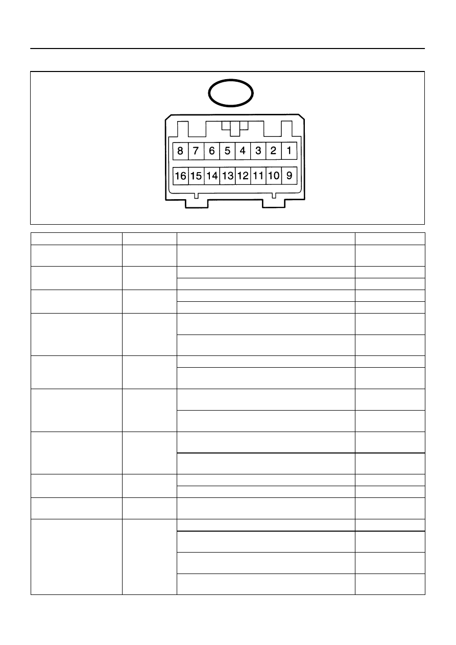
TERMINALS OF ECM

Symbols (Terminals No.)

Wiring Color

Condition

STD Voltage (V)

BATT 

 GND 

(C14–1 

 C14–16)

L–Y 

 W–B

Constant

10 – 16 V

STP– 

 GND 

G W

W B

Depress brake pedal

10 – 16 V

STP  

 GND 

(C14–2 

 C14–16)

G–W 

 W–B

Release brake pedal

Below 1 V

D

GND (C14 3

C14 16)

W R

W B

Shift to except D position

Below 1 V

 GND (C14–3 

 C14–16)

W–R 

 W–B

Shift to D position

10 – 16 V

PI

GND (C14 4

C14 16)

B Y

W B

Ignition switch ON

Cruise control main switch ON

Below 1.2 V

PI 

 GND (C14–4 

 C14–16)

B–Y 

 W–B

Ignition switch ON

Cruise control main switch OFF

10 – 16 V

TC

GND

Ignition switch ON

10 – 16 V

TC 

 GND

 (C14–5 

 C14–16)

Y–B 

 W–B

Ignition switch ON

Connect terminals TC and E1 of diagnostic check connector

Below 1 V

ECT 

 GND 

BR Y

W B

During driving 

Gear position 3rd

10 – 16 V

ECT 

 GND 

(C14–6 

 C14–16)

BR–Y 

 W–B

During driving 

Gear position O/D

Below 1 V

MC 

 GND 

LG B

W B

During cruise control driving

COAST switch hold ON

9 – 15 V

MC 

 GND 

(C14–7 

 C14–16)

LG–B 

 W–B

During cruise control driving

ACC switch hold ON

Below 1 V

 GND 

L B

W B

During cruise control driving

9 – 15 V

 GND 

(C14–8 

 C14–16)

L–B 

 W–B

Except during cruise control driving

Below 1 V

 GND 

(C14–9 

 C14–16)

 W–B

Ignition switch ON

10 – 16 V

Ignition switch ON

10 – 16 V

CCS

GND

Ignition switch ON

CANCEL switch hold ON

4.2 – 8.8 V

CCS 

 GND 

(C14–10 

 C14–16)

 W–B

Ignition switch ON

SET/COAST switch hold ON

2.5 – 6.3 V

Ignition switch ON

RES/ACC switch hold ON

0.8 – 3.7 V

DI–486

DIAGNOSTICS

CRUISE CONTROL SYSTEM

638

1997 LEXUS ES300   (RM511U)

Symbols (Terminals No.)

Wiring Color

Condition

STD Voltage (V)

CMS 

 GND 

G B

W B

Ignition switch ON

Main switch OFF

10 – 16 V

CMS 

 GND 

(C14–11 

 C14–16)

G–B 

 W–B

Ignition switch ON

Main switch ON

Below 0.5 V

SPD 

 GND 

(C14 12

C14 16)

G–O 

 W–B

Engine start

Stoppage a car.

Below 1.5 V or

4.7 – 16 V

(C14–12 

 C14–16)

G O 

 W B

During driving (Pulse generated).

3 – 7 V

IDL 

 GND 

Y L

W B

Ignition switch ON

Throttle valve fully opened.

10 – 16 V

IDL 

 GND 

(C14–13 

 C14–16)

Y–L 

 W–B

Ignition switch ON

Throttle valve fully closed.

Below 1.5 V

OD 

 GND

BR Y

W B

During cruise control driving

OD switch ON.

10 – 16 V

OD 

 GND

 (C14–14 

 C14–16)

BR–Y 

 W–B

During cruise control driving

OD switch OFF (3rd driving)

Below 1 V

MO 

 GND 

B W

W B

During cruise control driving

ACC switch hold ON

9 – 15 V

MO 

 GND 

(C14–15 

 C14–16)

B–W 

 W–B

During cruise control driving

COAST switch hold ON

Below 1 V

GND 

 Body  Ground

(C14–16 

 Body  Ground)

W–B 

 Body

Ground

Constant

Below 1 V

DI0EN–01

DIAGNOSTICS

CRUISE CONTROL SYSTEM

DI–487

639

1997 LEXUS ES300   (RM511U)

PROBLEM SYMPTOMS TABLE

Symptom

Suspect Area

See page

SET not occurring or CANCEL occurring.

(DTC is Normal)

1. Main Switch Circuit (Cruise control switch)

2. Vehicle Speed Sensor

3. Control Switch Circuit (Cruise control switch)

4. Stop Light Switch Circuit

5. Park/Neutral Position Switch Circuit

6. Actuator Motor Circuit

7. Cruise Control Cable

8. Cruise Control ECU

DI–519

DI–495

DI–499

DI–505

DI–511

DI–488

DI–525

IN–27

SET not occurring or CANCEL occurring.

(DTC dose not output)

1. ECU Power Source Circuit

2. Cruise Control ECU

DI–514

IN–27

Actual vehicle speed deviates above or below the set speed.

1. Cruise Control Cable

2. Vehicle Speed Signal Abnormal

3. Electronically  Controlled Transmission

 Communication Circuit

4. Actuator Motor Circuit

5. Idle Signal Circuit (main throttle position sensor)

6. Cruise Control ECU

DI–525

DI–498

DI–508

DI–488

DI–502

IN–27

Gear shifting frequent between 3rd O/D when driving on uphill

road. (Hurting)

1. Electronically  Controlled Transmission

 Communication Circuit

2. Cruise Control ECU

DI–508

IN–27

Cruise control not cancelled, even when brake pedal is de-

pressed.

1. Cruise Control Cable

2. Stop Light Switch Circuit

3. Actuator Motor Circuit

4. Cruise Control ECU

DI–525

DI–505

DI–488

IN–27

Cruise control not cancelled, even when transmission is shifted to

”N” position.

1. Cruise Control Cable

2. Park/Neutral Position Switch Circuit

3. Actuator Motor Circuit

4. Cruise Control ECU

DI–525

DI–511

DI–488

IN–27

Control switch does not operate.

(SET/COAST, ACC/RES, CANCEL not possible)

1. Cruise Control Cable

2. Control Switch Circuit

3. Actuator Motor Circuit

4. Cruise Control ECU

DI–525

DI–499

DI–488

IN–27

SET possible at 40 km/h (25 mph) or less, or CANCEL does not

operate at 40 km/h (25 mph) or less.

1. Cruise Control Cable

2. Vehicle Speed Signal Abnormal

3. Actuator Motor Circuit

4. Cruise Control ECU

DI–525

DI–498

DI–488

IN–27

Poor response is ACCEL and RESUME modes.

1. Cruise Control Cable

2. Electronically  Controlled Transmission

Communication Circuit

3. Actuator Motor Circuit

4. Cruise Control ECU

DI–525

DI–508

DI–488

IN–27

O/D does not RESUME, even though the road is not uphill.

1. Electronically  Controlled Transmission

 Communication Circuit

2. Cruise Control ECU

DI–508

IN–27

DTC memory is erased.

1. Back–up Power Source Circuit

2. Cruise Control ECU

DI–517

IN–27

DTC is not output, or is output when is should not be.

1. Diagnosis Circuit

2. Cruise Control ECU

DI–523

IN–27

Cruise MAIN indicator light remains ON or fall to light up.

Cruise MAIN Indicator Light Switch Circuit

DI–521

DI0EO–01

Duty Ratio =

A + B

A

x 100 (%)

ON

OFF

A

B

1 cycle

N21216

Cruise Control ECU

MO

7

MC

R–B

Cruise Control Actuator

R–G

1

2

15


Actuator Motor

C3

C3

C14

C14

DI–488

DIAGNOSTICS

CRUISE CONTROL SYSTEM

640

1997 LEXUS ES300   (RM511U)

CIRCUIT INSPECTION

DTC

11, 15

Actuator Motor Circuit

CIRCUIT DESCRIPTION

The actuator motor is operated by signals from the ECU. Acceleration and deceleration signals are trans-
mitted by changes in the Duty Ratio (See note below).
Duty Ratio
The duty ratio is the ratio of the period of continuity in one cycle. For example, if A is the period of continuity
in one cycle, and B is the period of non–continuity, then.

DTC No.

Detection Item

Trouble Area

11


Short in actuator motor circuit.


Actuator motor


Harness or connector between cruise control ECU and

actuator motor


Cruise control ECU

15


Open in actuator motor circuit.


Actuator motor

WIRING DIAGRAM


Content   ..  425  426  427  428   ..