Lexus ES300 (1997 year). Manual - part 391
 

  Index      Lexus     Lexus ES300 - service repair manual 1997 year


Search            


Content   ..  389  390  391  392   ..


Lexus ES300 (1997 year). Manual - part 391


R05897

R13006

AB0118 AB0119

W02043

H00014

Airbag Sensor
Assembly

P Squib

D Squib

Spiral
Cable

ACC

ON

or

DLC1

Code 12

E1

Tc

DIAGNOSTICS

SUPPLEMENTAL RESTRAINT SYSTEM

DI–341

493

1997 LEXUS ES300   (RM511U)

6

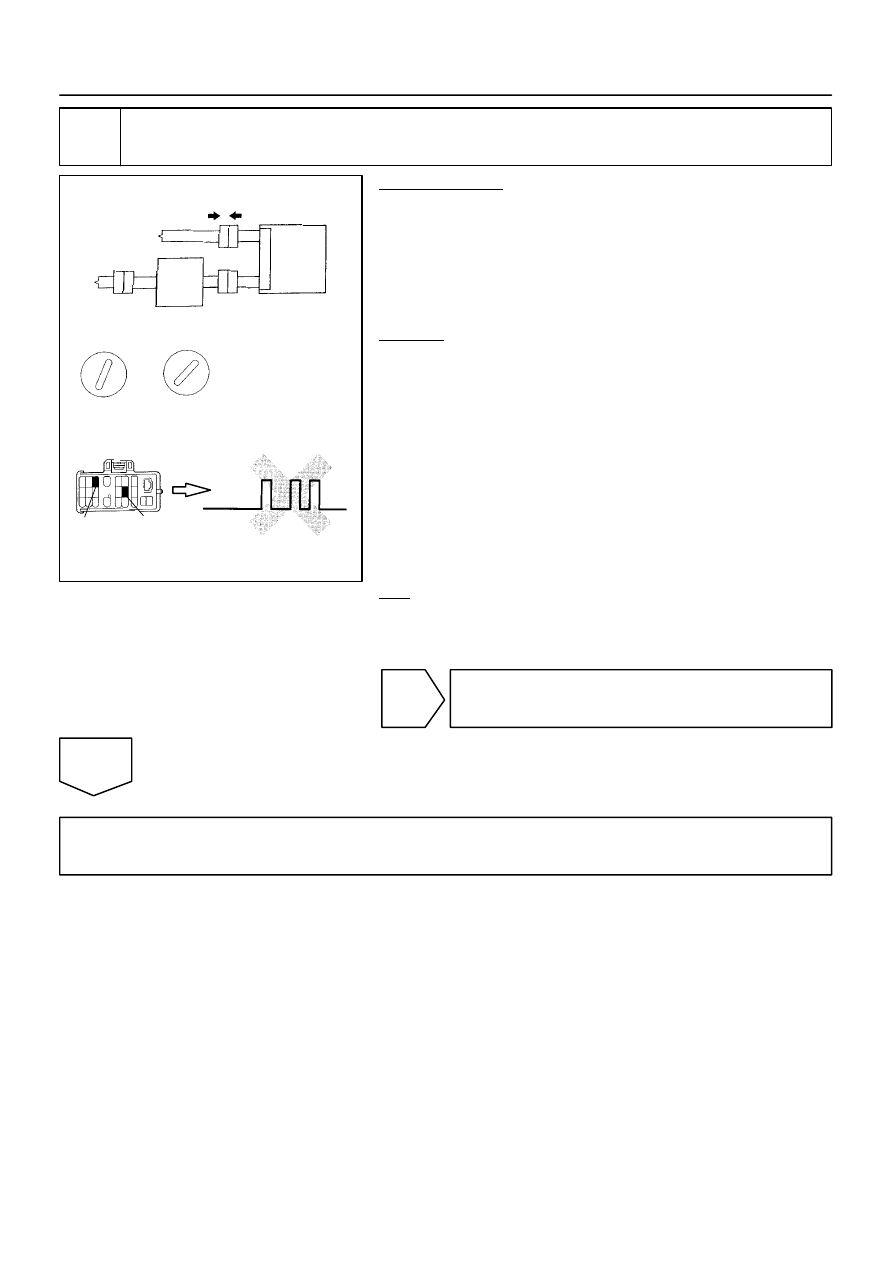
Check P squib.

PREPARATION:
(a)

Turn ignition switch to LOCK.

(b)

Disconnect negative (–) terminal cable from the battery,
and wait at least 90 seconds.

(c)

Connect front passenger airbag assembly connector.

(d)

Connect negative (–) terminal cable to battery, and wait
at least 2 seconds.

CHECK:
(a)

Turn ignition switch to ACC or ON, and wait at least 20 se-
conds.

(b)

Clear malfunction code stored in memory
(See page 

DI–324

).

(c)

Turn ignition switch to LOCK, and wait at least 20 se-
conds.

(d)

Turn ignition switch to ACC or ON, and wait at least 20 se-
conds.

(e)

Using SST, connect terminals Tc and E1 of DLC1.
SST 09843–18020

(f)

Check DTC.

OK:

DTC 12 is not output.

HINT:Codes other than code 12 may be output at this time, but
they are not relevant to this check.

NG

Replace front passenger airbag assembly.

OK

From the results of the above inspection, the malfunctioning part can now be considered normal.
To make sure of this, use the simulation method to check. 

R05899

AB0119

R14288

H00015

Airbag Sensor
Assembly

P Squib

D Squib

Spiral
Cable

D+

(+)

(–)

ON

DI–342

DIAGNOSTICS

SUPPLEMENTAL RESTRAINT SYSTEM

494

1997 LEXUS ES300   (RM511U)

7

Check spiral cable.

PREPARATION:
(a)

Turn ignition switch to LOCK.

(b)

Disconnect connector between airbag sensor assembly
and spiral cable.

(c)

Turn ignition switch ON.

CHECK:
Measure voltage at D+ on spiral cable side of connector be-
tween spiral cable and steering wheel pad and body ground.
OK:

Voltage: 0 V 

NG

Repair or replace spiral cable.

OK

Repair or replace harness or connector between airbag sensor assembly and spiral cable.

R15194

Airbag Sensor
Assembly

Spiral
Cable

D Squib

1

2

D+

D–

Y–B

Y

6

7

DIAGNOSTICS

SUPPLEMENTAL RESTRAINT SYSTEM

DI–343

495

1997 LEXUS ES300   (RM511U)

DTC

   13

Short in D Squib Circuit

CIRCUIT DESCRIPTION

The D squib circuit consists of the airbag sensor assembly, spiral cable and steering wheel pad. 
It causes the airbag to deploy when the airbag deployment conditions are satisfied.
For details of the function of each components, see OPERATION on page 

RS–2

DTC 13 is recorded when a short is detected in the D squib circuit.

DTC No.

DTC Detecting Condition

Trouble Area

13


Short circuit between D+ wire harness and D– wire har-

ness of squib


D squib malfunction


Spiral cable malfunction


Airbag sensor assembly malfunction


Steering wheel pad (D squib)


Spiral cable


Airbag sensor assembly


Wire harness

WIRING DIAGRAM

INSPECTION PROCEDURE

1

Preparation. (See step ” 1 ” on page 

DI–359

)

DI0B2–01

R05901

R14286

H00039

Airbag Sensor

Spiral
Cable

P Squib

D Squib

D+

D–

(+)

(–)

Assembly

R05902

AB0118

R13006

AB0119

FI1390

H00040

Airbag Sensor
Assembly

Spiral
Cable

D Squib

P Squib

ACC

ON

or

DLC1

E1

Tc

Code 13

DI–344

DIAGNOSTICS

SUPPLEMENTAL RESTRAINT SYSTEM

496

1997 LEXUS ES300   (RM511U)

2

Check D squib circuit.

PREPARATION:
Release airbag activation prevention mechanism on airbag
sensor assembly side of airbag squib connector
 (See page 

DI–324

).

CHECK:
For the connector (on the spiral cable side) between the spiral
cable and steering wheel pad, measure the resistance between
D+ and D–.
OK:

Resistance: 1 M

Ω 

 or Higher

NG

Go to step ” 5 ”.

OK

3

Check airbag sensor assembly.

PREPARATION:
(a)

Connect connector to the airbag sensor assembly.

(b)

Connect negative (–) terminal cable to battery, and wait
at least 2 seconds.

CHECK:
(a)

Turn ignition switch to ACC or ON and wait at least 20 se-
conds.

(b)

Clear malfunction code stored in memory
(See page 

DI–324

).

(c)

Turn ignition switch to LOCK, and wait at least 20 se-
conds.

(d)

Turn ignition switch to ACC or ON, and wait at least 20 se-
conds.

(e)

Using SST, connect terminals Tc and E1 of DLC 1.
SST 09843–18020

(f)

Check DTC.

OK:

DTC 13 is not output.

HINT:
Codes other than code 13 may be output at this time, but they
are relevant to this check.


Content   ..  389  390  391  392   ..