Lexus ES300 (1997 year). Manual - part 364
 

  Index      Lexus     Lexus ES300 - service repair manual 1997 year


Search            


Content   ..  362  363  364  365   ..


Lexus ES300 (1997 year). Manual - part 364


S05334

LEXUS
Hand–Held Tester

DLC2

BR3890

F00006

DLC1

Short Pin

N09348

Hand–Held Tester

Brake–Out–Box

ECU

LEXUS

LEXUS

DIAGNOSTICS

ANTI–LOCK BRAKE SYSTEM

DI–233

385

1997 LEXUS ES300   (RM511U)

(c)

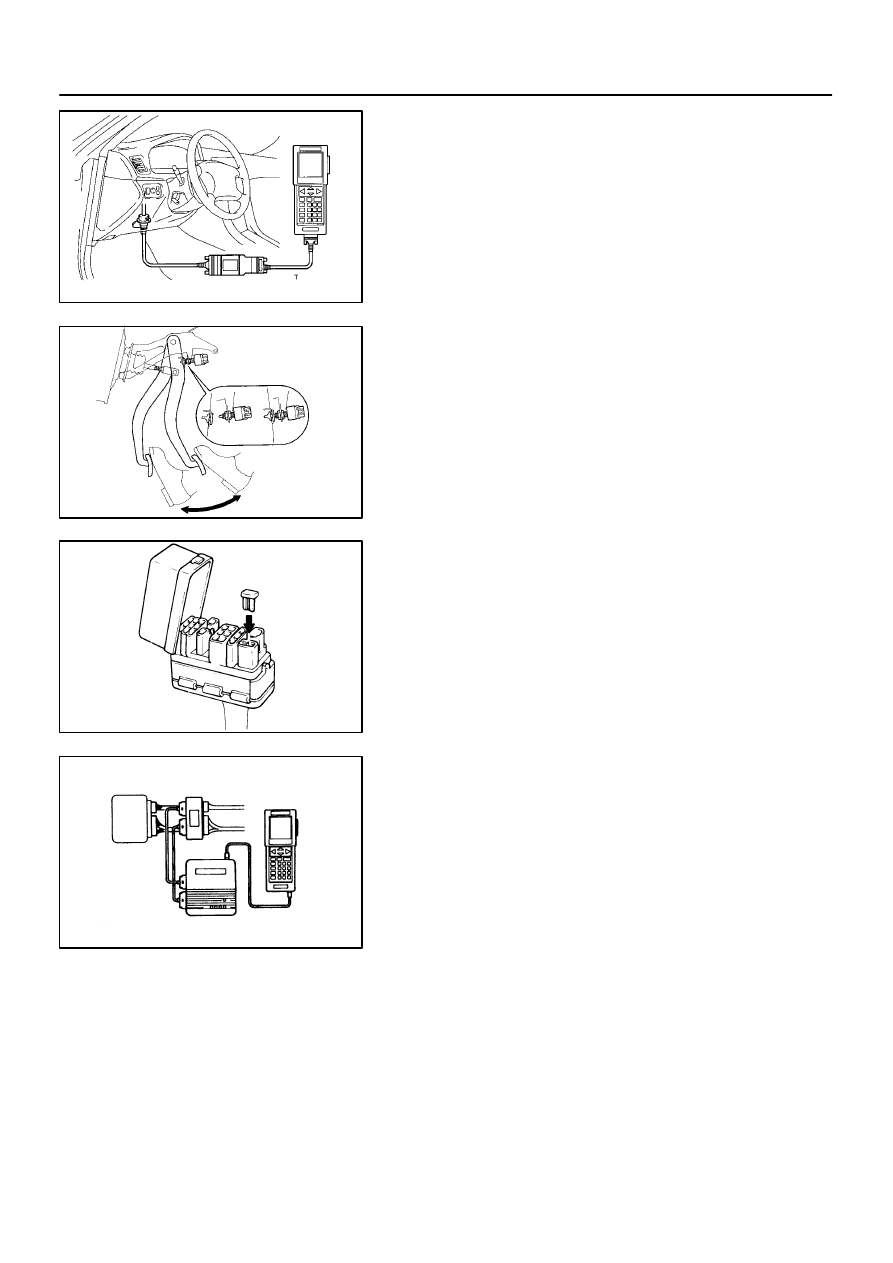
DTC CHECK USING LEXUS HAND–HELD TESTER
(1)

Hook up the LEXUS hand–held tester to the DLC2.

(2)

Read the DTC by following the prompts on the tes-
ter screen.
Please refer to the LEXUS hand–held tester opera-
tor’s manual for further details.

(d)

DTC CLEARANCE
(1)

Using SST, connect terminals Tc and E

1

 of DLC2 or

DLC1 and remove the short pin from DLC1.

SST

09843 – 18020

(2)

IG switch ON.

(3)

Clear the DTC stored in ECU by depressing the
brake pedal 8 or more times within 5 seconds.

(4)

Check that the warning light shows the normal
code.

(5)

Remove the SST from the terminals of DLC2 or
DLC1.

SST

09843 – 18020

(6)

Connect the short pin to DLC1.

(e)

ECU TERMINAL VALUES MEASUREMENT
USING LEXUS BREAK –OUT–BOX AND
LEXUS HAND–HELD TESTER
(1)

Hook up the LEXUS hand–held tester and 
LEXUS break–out–box to the vehicle.

(2)

Read the ECU input/output values by following the
prompts on the tester screen.

HINT:LEXUS hand–held tester has a ”Snapshot” function. This
records the measured values and is effective in the diagnosis
of intermittent problems.
Please refer to the LEXUS hand–held tester/LEXUS break–
out–box operator’s manual for further details.

F00007

DLC1

Ts

Tc

E

1

BR3904

0.13 sec.

0.13 sec.

ON

OFF

BR3893

Malfunction Code (Example Code 72, 76)

7

2

6

7

ON

OFF

0.5 sec.

0.5 sec.

0.5 sec.

0.5 sec.

1.5 sec.

2.5 sec.

4 sec.

Repeat

S05334

LEXUS
Hand–Held Tester

DLC2

DI–234

DIAGNOSTICS

ANTI–LOCK BRAKE SYSTEM

386

1997 LEXUS ES300   (RM511U)

2.

SPEED SENSOR SIGNAL

(a)

SPEED SENSOR SIGNAL CHECK
(1)

Turn the ignition switch OFF.

(2)

Using SST, connect terminals Ts and E

1

 of DLC1.

SST

09843 – 18020

(3)

Start the engine.

(4)

Check that the ABS warning light blinks.

HINT:If the ABS warning light does not blink, inspect the ABS
warning light circuit (See page 

DI–262

).

(5)

Drive vehicle straight forward.

HINT:Drive vehicle faster than 45 km/h (28 mph) for several se-
conds.

(6)

Stop the vehicle.

(7)

Using SST, connect terminals Tc and E

1

 of DLC1.

SST

09843 – 18020

(8)

Read the number of blinks of the ABS warning light.

HINT:See the list of DTC shown on the next page.
If every sensor is normal, a normal code is output (A cycle of
0.25 sec. ON and 0.25 sec. OFF is repeated).
If 2 or more malfunction are indicated at the same time, the low-
est numbered code will be displayed 1st.

(9)

After doing the check, disconnect the SST from ter-
minals Ts and E

1

, Tc and E

of DLC1, and turn igni-

tion switch OFF.

SST

09843 – 18020

(b)

DTC CHECK USING LEXUS HAND–HELD TESTER
(1)

Do step 1. 

 6. on the previous page.

(2)

Hook up the LEXUS hand–held tester to the DLC2.

(3)

Read the DTC by following the prompts on the tes-
ter screen.
Please refer to the LEXUS hand–held tester opera-
tor’s manual for further details.

DIAGNOSTICS

ANTI–LOCK BRAKE SYSTEM

DI–235

387

1997 LEXUS ES300   (RM511U)

(c)

DTC OF SPEED SENSOR CHECK FUNCTION

Code No.

Diagnosis

Trouble Area

71

Low output voltage of right front speed sensor


Right front speed sensor


Sensor installation


Right front speed sensor rotor

72

Low output voltage of left front speed sensor


Left front speed sensor


Sensor installation


Left front speed sensor rotor

73

Low output voltage of right rear speed sensor


Right rear speed sensor


Sensor installation


Right rear speed sensor rotor

74

Low output voltage of left rear speed sensor


Left rear speed sensor


Sensor installation


Left rear speed sensor rotor

75

Abnormal change in output voltage of right front speed sen-

sor


Right front speed sensor rotor

76

Abnormal change in output voltage of left front speed 

sensor


Left front speed sensor rotor

77

Abnormal change in output voltage of right rear speed 

sensor


Right rear speed sensor rotor

78

Abnormal change in output voltage of left rear speed sensor


Left rear speed sensor rotor

DI0BE–01

DI–236

DIAGNOSTICS

ANTI–LOCK BRAKE SYSTEM

388

1997 LEXUS ES300   (RM511U)

DIAGNOSTIC TROUBLE CODE CHART

HINT:Using SST 09843 –18020, connect the terminals Tc and E

1

, and remove the short pin.

If a malfunction code is displayed during the DTC check, check the circuit listed that the code. For details
of each code, turn to the page referred to under the ”See page” for respective ”DTC No.” in the DTC chart.

DTC No.

(See Page)

Detection Item

Trouble Area

11

(

DI–240

)

Open circuit in ABS solenoid relay circuit


ABS solenoid relay

12

(

DI–240

)

Short circuit in ABS solenoid relay circuit


ABS solenoid relay


ABS solenoid relay circuit

13

(

DI–243

)

Open circuit in ABS motor relay circuit


ABS motor relay

14

(

DI–243

)

Short circuit in ABS motor relay circuit


ABS motor relay


ABS motor relay circuit

21

(

DI–246

)

Open or short circuit in 2–position solenoid circuit for right front

wheel


ABS actuator


SFRR or SFRH circuit

22

(

DI–246

)

Open or short circuit in 2–position solenoid circuit for left front

wheel


ABS actuator


SFLR or SFLH circuit

23

(

DI–246

)

Open or short circuit in 2–position solenoid circuit for right rear

wheel


ABS actuator


SRRR or SRRH circuit

24

(

DI–246

)

Open or short circuit in 2–position solenoid circuit for left rear

wheel


ABS actuator


SRLR or SRLH circuit

31

(

DI–248

)

Right front wheel speed sensor signal malfunction

32

(

DI–248

)

Left front wheel speed sensor signal malfunction


Right front, left front, right rear and left rear speed sensor

E

h

d

i

it

33

(

DI–248

)

Right rear wheel speed sensor signal malfunction


Each speed sensor circuit


Speed sensor rotor

34

(

DI–248

)

Left rear wheel speed sensor signal malfunction

33, 34

(

DI–253

)

Rear speed sensor rotor faulty


Rear axle hub


Right rear, left rear speed sensor


Rear speed sensor circuit

41

(

DI–254

)

Power source voltage down


Battery


IC regulator


Power source circuit

49

(

DI–257

)

Open circuit in stop light switch circuit


Stop light switch


Stop light switch circuit

51

(

DI–259

)

Pump motor is locked


ABS pump motor

Always ON

(

DI–260

)

Malfunction in ECU


ECU


Battery


Content   ..  362  363  364  365   ..