Lexus LS400 (2000 year). Manual - part 86
A02860
A04475
A03218
No.2 Idler Pulley Bolt
Timing
Mark
Crankshaft
Pulley Bolt
A02852
Rotate (25
°
)
–
ENGINE MECHANICAL
CYLINDER HEAD
EM–37
1219
13.
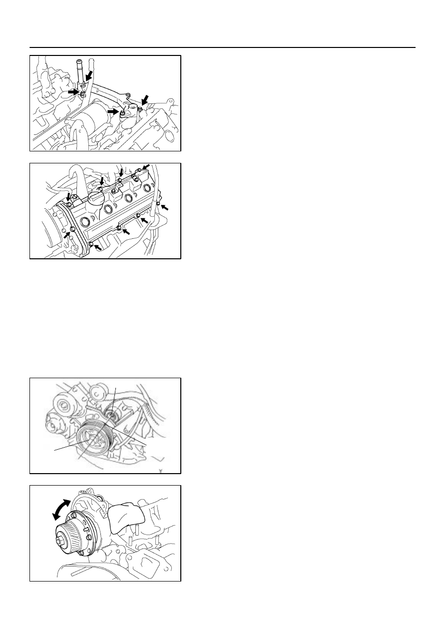
REMOVE REAR WATER BYPASS JOINT
Remove the 4 nuts, water bypass joint and 2 gaskets.
14.
REMOVE VVT SENSORS
15.
REMOVE ENGINE HANGERS
16.
REMOVE OIL DIPSTICK AND GUIDE FOR A/T
(See page
17.
REMOVE OIL DIPSTICK AND GUIDE FOR ENGINE
(See page
18.
REMOVE CYLINDER HEAD COVERS
Remove the 9 bolts, 9 seal washers, cylinder head cover and
gasket. Remove the 2 cylinder head covers.
19.
IF NECESSARY, REMOVE SEMI–CIRCULAR PLUGS
AND CAMSHAFT HOUSING PLUGS
20.
REMOVE CAMSHAFT TIMING OIL CONTROL VALVE
(See page
21.
REMOVE CAMSHAFTS
NOTICE:
Since the thrust clearance of the camshaft is small, the
camshaft must be kept level while it is being removed. If the
camshaft is not kept level, the portion of the cylinder head
receiving the shaft thrust may crack or be damaged, caus-
ing the camshaft to seize or break. To avoid this, the follow-
ing steps should be carried out.
(a)
Check the crankshaft pulley position.
Check that the timing mark of the crankshaft pulley is in
aligned with the centers of the crankshaft pulley bolt and
idler pulley bolt.
NOTICE:
Having the crankshaft pulley at the wrong angle can cause
the piston head and valve head to come into contact with
each other when you remove the camshaft, causing dam-
age. So always set the crankshaft pulley at the correct
angle.
(b)
Rotate the VVT–i pulley from left to right 2 to 3 times within
its range of movement (25
°
<50
°
CA> ) and use a waste
cloth to collect the oil from the camshaft timing oil control
valve installation hole.
NOTICE:
Approximately 20 cc (1.2 cu in.) of oil will be ejected, so
take care not to spill it.