Lexus LS400 (2000 year). Manual - part 39
N13434
–
BODY ELECTRICAL
POWER SOURCE
BE–25
1888
3.
RELAY CIRCUIT
Remove the relay from the junction block and inspect the con-
nector on junction block side.
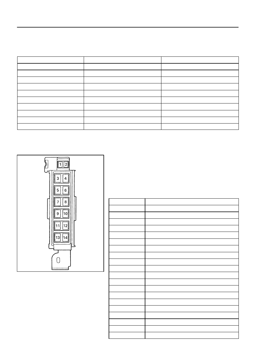
Connect numbers are shown in the illustration.
Relay
Tester connection
Condition
Specified condition
Taillight Control
(2) – Ground
Light control switch TAIL or HEAD
Continuity
Taillight Control
(3) – Ground
Constant
Continuity
Taillight Control
(1) – Ground
Constant
Battery positive voltage
Taillight Control
(4) – Ground
Constant
Battery positive voltage
Ignition Main
(6) – Ground
Constant
Continuity
Ignition Main
(7) – Ground
Constant
Continuity
Ignition Main
(5) – Ground
Ignition switch ON
Battery positive voltage
Power Main
(12) – Ground
Constant
Battery positive voltage
Fog Light Control
(13) – Ground
Light control switch HEAD
Battery positive voltage
Fog Light Control
(16) – Ground
Constant
Battery positive voltage
If the circuit is not as specified, inspect the circuits connected
to other parts.
4.
Bolted type:
FUSIBLE LINK CIRCUIT
(a)
Remove the battery.
(b)
Remove the fusible link set bolts.
(c)
Inspect the continuity between terminals and connected
parts.
(d)
Connect numbers are shown in the illustration.
Terminal
Connected parts
1
Ignition switch
2
Battery positive voltage
3
ALT–S Fuse
3
ST Fuse
3
HORN Fuse
3
HAZ Fuse
3
EFI Fuse
3
RADIO Fuse
3
TEL Fuse
3
SRS Fuse
4
Battery positive voltage
6
Battery positive voltage
6
HTR H–Fuse
6
AM1 H–Fuse
6
ABS H–Fuse
6
DEF H–Fuse
6
H/CTRL H–Fuse
6
FOG Fuse
6
STOP Fuse
6
OBD Fuse