Lexus LS400 (2000 year). Manual - part 30
Z14905
BE0CU–01
N13349
Z14753
Wire Harness Side
–
BODY ELECTRICAL
SEAT HEATER SYSTEM
BE–197
2060
INSPECTION
1.
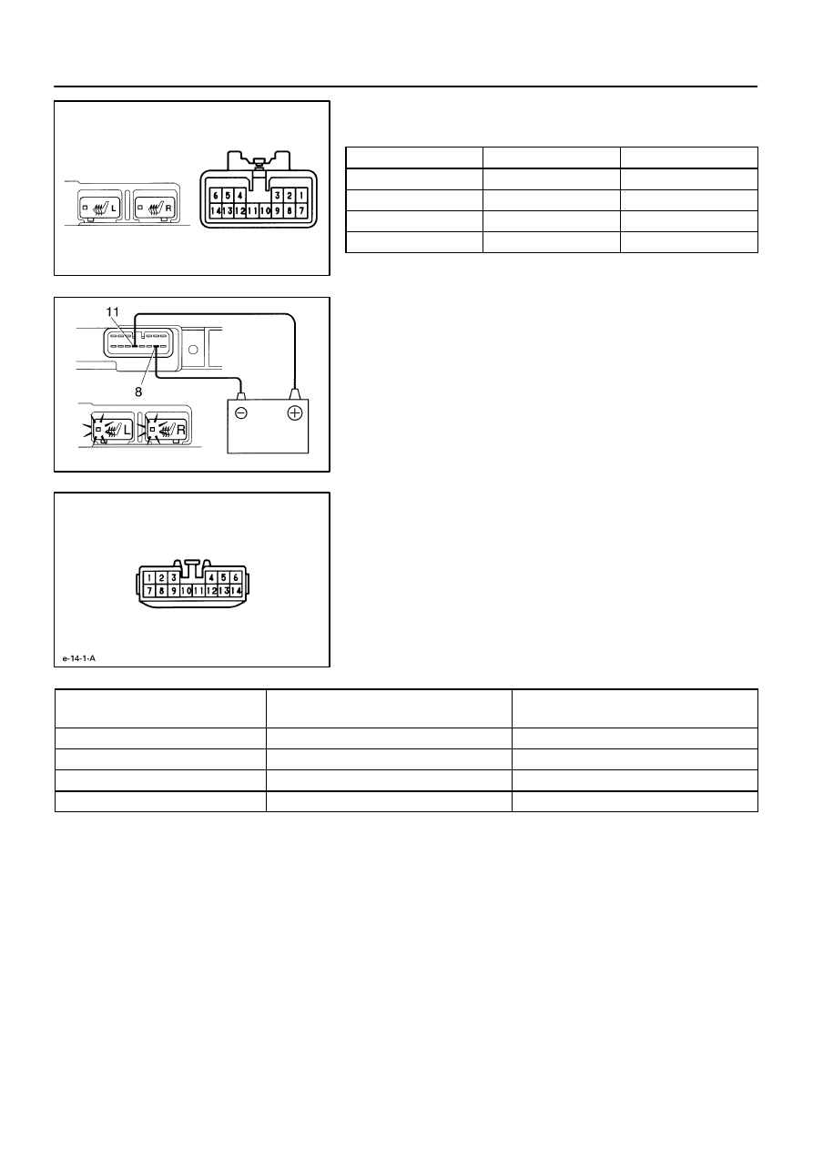
INSPECT SEAT HEATER SWITCH CONTINUITY
Condition
Tester connection
Specified condition
OFF
–
No continuity
ON (Left)
8 – 9 – 11
Continuity
ON (Right)
8 – 11 – 13
Continuity
Illumination
10 – 12
Continuity
If continuity is not as specified, replace the switch or bulb.
2.
INSPECT SEAT HEATER SWITCH INDICATOR
(a)
Connect the positive (+) lead from the battery to terminal
11 and the negative (–) lead to terminal 8.
(b)
Push the switch and check that the indicator light lights
up.
If operation is not as specified, replace the switch.
3.
INSPECT SEAT HEATER SWITCH CIRCUIT
Disconnect the switch connector and inspect the connector on
the wire harness side, as shown.
Tester connection to
terminal number
Condition
Specified condition
8 – Ground
Constant
Continuity
9 – Ground
Constant
* Continuity
13 – Ground
Constant
* Continuity
11 – Ground
Ignition switch turned to ON
Battery positive voltage
*: There is resistance because this circuit is grounded through
the relay coil.
If circuit is not as specified, inspect the circuits connected to oth-
er parts.