Lexus LS400 (2000 year). Manual - part 19
BE–158
–
BODY ELECTRICAL
WIRELESS DOOR LOCK CONTROL SYSTEM
2021
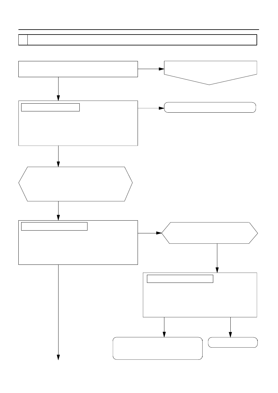
Disconnect the connector of wireless door lock
control cancel switch (buzzer switch) and
connect the tester between connector terminal 2
on the wire harness side and body ground.
(voltage range)
After turning wireless door lock control cancel switch
(buzzer switch) ON, when operating each switch under
the standard operation, check that the buzzer chirps
once (locked) twice (unlocked) and once (luggage
door unlocked).
No
Yes
2 Wireless door lock buzzer does not chirp.
When performing UNLOCK – LOCK operation with
wireless door lock function, check voltage of more than
10 V is output once (locked), twice (unlocked) and
once (luggage door unlocked).
(Check the voltage in the bar graph.)
No
Chirping operation check:
Check that door LOCK and UNLOCK function normally
with wireless door lock function.
Proceed to chart 1 or chart 2.
(Wireless door lock function faulty.)
No
Yes
Normal.
MPX body ECU output check:
Yes
Connect the tester between connector
terminal 3 of MPX body ECU and
body ground. (voltage range)
When performing UNLOCK – LOCK operation with
wireless door lock function, check voltage of more
than 10 V is output once (locked), twice (unlocked)
and once (luggage door unlocked).
(Check the voltage in the bar graph.)
MPX body ECU output check:
MPX body ECU faulty.
MPX body ECU faulty.
Wireless door lock control cancel switch
(buzzer switch) wire harness side faulty.
Yes
No