Lexus GS300/400 (2000 year). Manual - part 231
 

  Index      Lexus     Lexus GS300/400 - service repair manual 2000 year


Search            


Content   ..  229  230  231  232   ..


Lexus GS300/400 (2000 year). Manual - part 231


F03674

SST

IN

OUT

Pressure Feed Tube

Attachment

2JZ–GE:

1UZ–FE:

Attachment

OUT

IN

Pressure Feed Tube

STEERING

POWER STEERING FLUID

SR–5

2175

2.

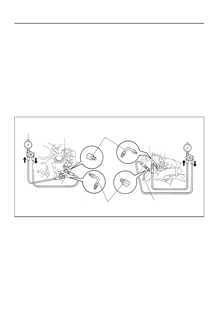
CHECK STEERING FLUID PRESSURE

(a)

1UZ–FE:
Remove the air cleaner inlet.

(b)

1UZ–FE:
Remove the air cleaner assembly with air cleaner hose.
(See page 

SR–31

)

(c)

Disconnect the pressure feed tube from the PS vane
pump.
(2JZ–GE Engine: See page 

SR–21

)

(1UZ–FE Engine: See page 

SR–31

)

SST

09631–22020

(d)

Connect SST, as shown below.
SST

09640–10010 (09641–01010, 09641–01030,
09641–01060)

NOTICE:
Check that the valve of the SST is in the open position.

(e)

Bleed the power steering system.
(See page 

SR–3

)

(f)

Start the engine and run it at idle.

(g)

Turn the steering wheel from lock to lock several times to
boost fluid temperature.
Fluid temperature: 80 

°

C (176 

°

F)

Z15498

PS Gear

Closed

SST

PS Vane
Pump

Oil
Reservoir

Z15499

PS Gear

SST

PS Vane
Pump

Oil
Reservoir

Open

Z15500

PS Gear

SST

PS Vane
Pump

Oil
Reservoir

Open

Lock Position

SR–6

STEERING

POWER STEERING FLUID

2176

(h)

With the engine idling, close the valve of the SST and ob-
serve the reading on the SST.
Minimum fluid pressure:
8,336 kPa (85 kgf/cm

2

, 1,209 psi)

NOTICE:


Do not keep the valve closed for more than 10 se-
conds.


Do not let the fluid temperature become too high.

(i)

With the engine idling, open the valve fully.

(j)

Measure the fluid pressure at engine speeds of 1,000 rpm
and 3,000 rpm.
Difference fluid pressure:
490 kPa (5 kgf/cm

2

, 71 psi) or less

NOTICE:
Do not turn the steering wheel.

(k)

With the engine idling and valve fully opened, turn the
steering wheel to full lock.
Minimum fluid pressure:
8,336 kPa (85 kgf/cm

2

, 1,209 psi)

NOTICE:


Do not maintain lock position for more than 10 se-
conds.


Do not let the fluid temperature become too high.

(l)

Disconnect the SST.

(m)

Connect the pressure feed tube.
(2JZ–GE Engine: See page 

SR–28

)

(1UZ–FE Engine: See page 

SR–41

)

(n)

1UZ–FE Engine:
Install the air cleaner assembly with air cleaner hose.
(See page 

SR–41

)

(o)

1UZ–FE Engine:
Install the air cleaner inlet.

(p)

Bleed the power steering system.
(See page 

SR–3

)

SR0E2–01

F03672


 Clip

Grommet

Bracket

65 (660, 48)

87 (890, 64)

5 (55, 48 in.·lbf)

42 (430, 31)

Intermediate Shaft
Assembly

PS Gear Assembly

Return Tube

Pressure Feed Tube

Tube Clamp

Union Bolt

N·m (kgf·cm, ft·lbf) : Specified torque


 Non–reusable part

2JZ–GE:

42 (430, 31)

Union Bolt

5 (55, 48 in.·lbf)

Tube Clamp

Return
Tube


 Gasket


 Gasket

Pressure Feed Tube


 Clip

87 (890, 64)

65 (660, 48)

35 (360, 26)

SR–42

STEERING

POWER STEERING GEAR

2212

POWER STEERING GEAR

COMPONENTS

F03664

Tie Rod End

Lock Nut

Rack Boot


 Claw Washer

Steering Rack


 Claw Washer

Rack Housing

Clip


 Clamp


 O–Ring

Bushing


 Oil Seal

Spacer

Cylinder End
Stopper


O–Ring


 Teflon Ring


 Oil Seal

Rack End


 Clamp

Rack Boot

Clip

Lock Nut

Tie Rod End

N·m (kgf·cm, ft·lbf) : Specified torque


Non–reusable part

Molybdenum disulfide lithium base grease
Power Steering fluid

*For use with SST

55 (560, 41)

55 (560, 41)

103 (1,050, 76)

*76 (770, 56)

103 (1,050, 76)

*76 (770, 56)

59 (600, 43)

Rack End

STEERING

POWER STEERING GEAR

SR–43

2213


Content   ..  229  230  231  232   ..