Lexus GS300/400 (2000 year). Manual - part 79
 

  Index      Lexus     Lexus GS300/400 - service repair manual 2000 year


Search            


Content   ..  77  78  79  80   ..


Lexus GS300/400 (2000 year). Manual - part 79


BE01L–11

I01349

Ignition Switch

Key Unlock Warning Switch

BE–30

BODY ELECTRICAL

IGNITION SWITCH AND KEY UNLOCK WARNING 
SWITCH

2331

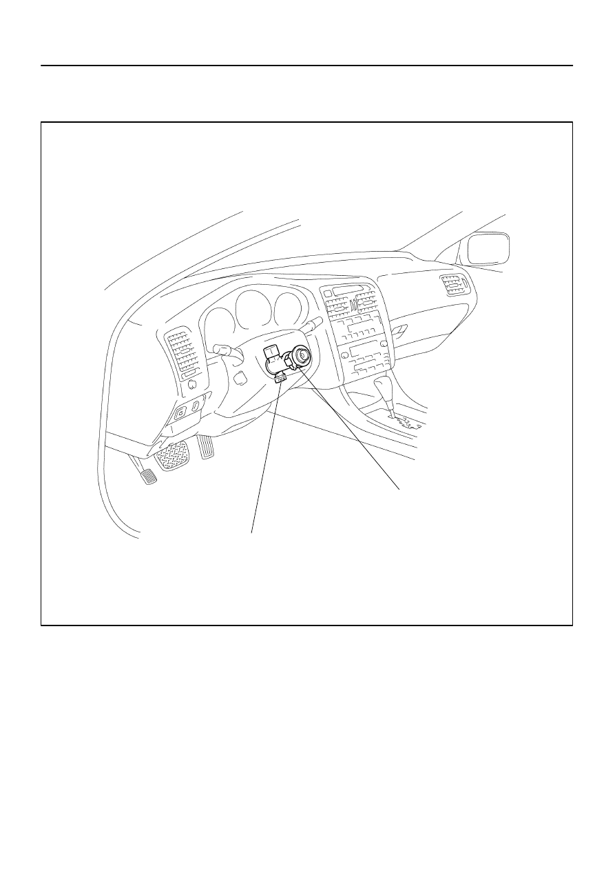
IGNITION SWITCH AND KEY UNLOCK WARNING SWITCH

LOCATION

BE0H4–04

I01256

1

2

3

4

5

6

7

8

LOCK

ACC

ON

START

I04031

From Back Side

BODY ELECTRICAL

IGNITION SWITCH AND KEY UNLOCK WARNING 
SWITCH

BE–31

2332

INSPECTION

1.

INSPECT IGNITION SWITCH CONTINUITY

Switch position

Tester connection

Specified condition

LOCK

No continuity

ACC

2 – 3

Continuity

ON

2 – 3 – 4

6 – 7

Continuity

START

1 – 2 – 4

6 – 7 – 8

Continuity

If continuity is not as specified, replace the switch.

2.

INSPECT IGNITION SWITCH CIRCUIT

Connect the switch connector and inspect the connector on
wire harness side from the back side, as shown.

Tester connection

Condition

Specified condition

2 – Ground

Constant

Battery positive voltage

3 – Ground

Ignition switch ACC or ON

Battery positive voltage

4 – Ground

Ignition switch ON

Battery positive voltage

6 – Ground

Ignition switch ON or START

Battery positive voltage

7 – Ground

Constant

Battery positive voltage

8 – Ground

Ignition switch START

Battery positive voltage

If circuit is not as specified, inspect the circuits connected to oth-
er parts.

I04265

I01663

1

2

OFF

ON

3

4

I04032

Wire Harness Side

BE–32

BODY ELECTRICAL

IGNITION SWITCH AND KEY UNLOCK WARNING 
SWITCH

2333

3.

INSPECT IGNITION KEY ILLUMINATION OPERATION

Connect the positive (+) lead from the battery to terminal 1 and
the negative (–) lead to terminal 2, and check that the indicator
light lights up.
If operation is not as specified, replace the switch.
4.

INSPECT IGNITION KEY ILLUMINATION CIRCUIT
(See page 

DI–843

)

5.

INSPECT KEY UNLOCK WARNING SWITCH CONTI-
NUITY

Switch position

Tester connection

Specified condition

OFF (Key removed)

No continuity

ON (Key set)

1 – 2

Continuity

If continuity is not as specified, replace the switch.

6.

INSPECT KEY UNLOCK WARNING SWITCH CIRCUIT
(See page 

DI–828

)

Connect the switch connector and inspect the connector on
wire harness side from the back side, as shown.

Tester connection

Condition

Specified condition

1 – Ground

Constant

Continuity

If circuit is not as specified, inspect the circuits connected to oth-
er parts.

BE0H8–04

I10257

Driver Side Junction Block


 GAUGE Fuse


 TAIL Fuse


 Taillight Control Relay


 Body ECU No.2

Combination Switch


 Light Control Switch


 Headlight Dimmer Switch

Ignition Switch

Daytime Running
Light Main Relay
(w/ D.R.L. System)

Headlights

Engine Room No.1 Junction Block


 H–LP L LWR Fuse


 H–LP R LWR Fuse


 H–LP L UPR Fuse (w/o D.R.L System)


 H–LP R UPR Fuse (w/o D.R.L System)


 Headight Control Relay

D.R.L.: Daytime Running Light

Automatic Light Control Sensor

Headlights

Taillights

Engine Room No.2 Junction Block


 Headight Dimmer (D.R.L. No.2) Relay


 H–LP R UPR Fuse (w/ D.R.L System)


 H–LP L UPR Fuse (w/ D.R.L System)

Light Control ECU

Light Control ECU

Daytime Running Light No.3 and No.4 Relay
(w/ D.R.L. System)

Daytime Running Light Resister

BODY ELECTRICAL

HEADLIGHT AND TAILLIGHT SYSTEM

BE–33

2334

HEADLIGHT AND TAILLIGHT SYSTEM

LOCATION


The vehicle shown in this illustration is ”GS400”.


All components of ”GS300” other than the ones used for engine are same as ”GS400”.


Content   ..  77  78  79  80   ..