Lexus GS300/400 (2000 year). Manual - part 56
BE0HD–04
I05186
”Bright”
”Dark”
1
2
3
4
Black coloured tape
I04048
Wire Harnes Side
BE–182
–
BODY ELECTRICAL
ELECTRO CHROMIC MIRROR SYSTEM
2483
INSPECTION
1.
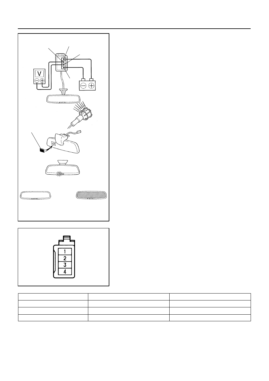
INSPECT ELECTRO CHROMIC INNER MIRROR OP-
ERATION
(a)
Connect the positive (+) lead from the battery to terminal
1 and the negative (–) lead to terminal 4.
(b)
Connect the positive (+) lead from the voltmeter to termi-
nal 2 and the negative (–) lead to terminal 3.
(c)
Attach a black coloured tape to forward sensor to prevent
it from sensing.
(d)
When the mode is turned to AUTO, check that indicator
light lights up.
(e)
Light up the mirror with an electric light, and check that
there is battery positive voltage and mirror surface
changes ”bright” to ”dark”.
If operation is not as specified, replace the inner mirror.
2.
INSPECT ELECTRO CHROMIC INNER MIRROR CIR-
CUIT
Disconnect the connector from the mirror and inspect the con-
nector on the wire harness side, as shown.
Tester connection
Condition
Specified condition
4 – Ground
Constant
Continuity
1 – Ground
Ignition switch LOCK or ACC
No voltage
1 – Ground
Ignition switch ON
Battery positive voltage
If circuit is not as specified, inspect the circuits connected to
other parts.