Land Rover V8 engine. Manual - part 4


  Index      Land Rover     Land Rover V8 engine (3.5, 3.9, 4.2 Litre) - service repair 1996 year


Search            


Content   ..  1  2  3  4  5  ..


Land Rover V8 engine. Manual - part 4


ENGINE

2

OVERHAUL

Dismantle

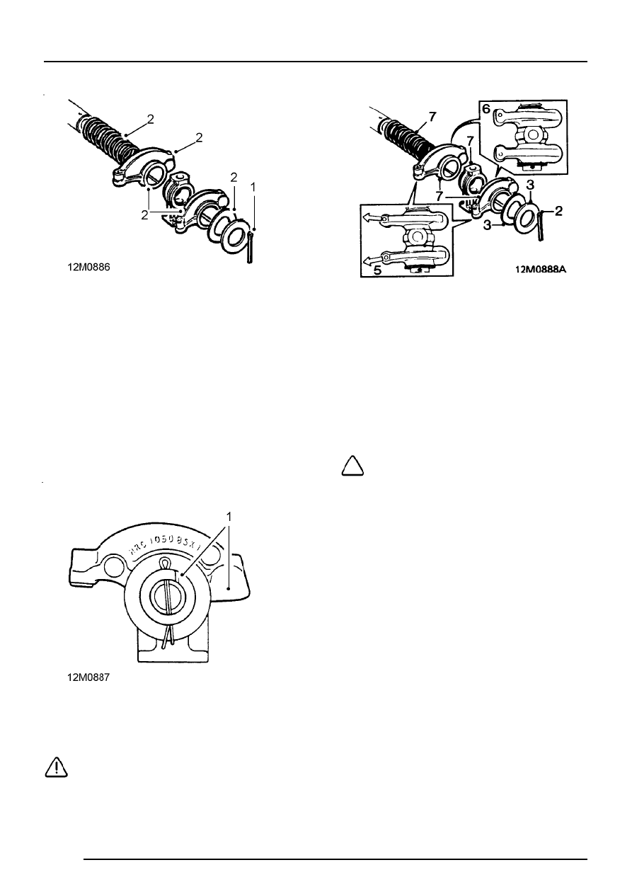
1. Remove split pin from one end of rocker shaft.
2. Remove plain washer, wave washer, rocker

arms, brackets and springs.

Inspect

1. Thoroughly clean components.
2. Inspect each component for wear, in particular

rocker arms and shafts. Discard weak or
broken springs.

3. Inspect pushrod seats in rocker arms.
4. Check pushrods for straightness and inspect

ball ends for damage, replace as necessary.

Assembly

1. Assemble rocker shafts with identification

groove at one o’clock position with push rod
end of rocker arm to the right.

CAUTION: If rocker shafts are incorrectly
assembled and fitted to engine, oil supply
to rocker arms will be restricted.

2. Fit new split pin to one end of rocker shaft.
3. Fit plain washer and wave washer.
4. Lubricate rocker arm bushes with clean engine

oil.

5. Early type rocker arms are angled, and must

be fitted with the valve end of the rocker arms
angled away from each other as illustrated.

6. On later type rocker arms the valve end is

offset and must be fitted as illustrated.

NOTE: Early and late rocker arms are
interchangeable provided the complete set
is changed.

7. Assemble rocker arms, brackets and springs to

rocker shaft.

8. Compress springs, fit wave washer, plain

washer and secure with new split pin.

ENGINE

OVERHAUL

3

Rocker shaft - refit

1. Lubricate pushrods with engine oil.
2. Fit pushrods in removed order.

3. Fit each rocker shaft assembly, ensuring

identification groove is uppermost and towards
front of engine on RH side and towards rear of
engine on LH side.

CAUTION: Incorrect fitment will result in
an oil feed restriction.

4. Fit bolts and tighten to correct torque.
5. Clean gasket surface in rocker cover using

Bostik cleaner 6001 or equivalent, and allow to
dry.

6. Apply a thin coating of Bostik 1775 or

equivalent impact adhesive to mating surfaces
of rocker cover and gasket.

7. Allow adhesive to cure, then fit gasket to rocker

cover.

CAUTION: Gasket fits one way round only,
it must be fitted accurately as subsequent
movement will destroy bonding.

8. Fit rocker cover to cylinder head, fit screws and

tighten to correct torque.

CAUTION: The 2 short screws must be
fitted on side of cover nearest centre of
engine.

9. LH rocker shaft only: Align dipstick tube to

rocker cover, fit and tighten screw.

ENGINE

4

OVERHAUL

CYLINDER HEAD

Cylinder head - remove

1. Remove rocker shaft assembly.
2. Mark heads LH and RH for reassembly.

Engine numbers without suffix B

NOTE: RH cylinder head illustrated

3. Using sequence shown, remove 14 bolts

securing cylinder head to cylinder block.

Engine numbers with suffix B

NOTE: RH cylinder head illustrated

4. Using sequence shown, remove and discard

10 bolts securing cylinder head to cylinder
block.

NOTE: No bolts are fitted in the four lower
holes in each cylinder head.

All engines

5. Release cylinder head from 2 dowels and

remove cylinder head.

6. Remove and discard cylinder head gasket.

Valves and springs - remove

1. Remove spark plugs.

2. Using valve spring compressor LRT-12-034 or

a suitable alternative, compress valve spring.

3. Remove 2 collets.

4. Release spring compressor and remove valve,

valve spring cap and valve spring.

5. Repeat above operations for remaining valves.

CAUTION: Keep valves, springs, caps and
collets in fitted order.

6. Remove and discard valve stem oil seals.

ENGINE

OVERHAUL

5

Valves, valve springs and guides - inspection

1. Clean cylinder head, valve springs, valves and

valve guide bores.

2. Check existing valve stem and head diameters.
3. Check valve stem to guide clearance using

new valves.

4. Renew valves and guides as necessary.

Valve head diameter A:
Inlet = 39.75 to 40.00 mm
Exhaust = 34.226 to 34.48 mm
Valve stem diameter B:
Inlet = 8.664 to 8.679 mm
Exhaust = 8.651 to 8.666 mm

5. Check installed height of each valve.

Valve installed height C= 47.63 mm

6. Renew valve/valve seat insert as necessary.

7. Check valve stem to guide clearance.

Valve stem to guide clearance D:
Inlet = 0.25 to 0.66 mm
Exhaust = 0.38 to 0.78 mm

8. Check condition of valve springs:

Free length = 48.30 mm
Fitted length = 40.40 mm
Load at fitted length = 339

±

10N

Load at valve open length = 736

±

22N

CAUTION: Valve springs must be replaced
as a complete set.

Valve guide - renew

1. Using valve guide remover, LRT-12-037 press

valve guide out from combustion chamber side
of cylinder head.

NOTE: Service valve guides are 0.025mm
oversize on outside diameter to ensure
interference fit.

2. Lubricate new valve guide with engine oil and

place in position.


Content   ..  1  2  3  4  5  ..