Land Rover engine 300 TDi. Manual - part 6


  Index      Land Rover     Land Rover engine 300 TDi - service manual 1995 year


Search            


Content   ..  4  5  6  7   ..


Land Rover engine 300 TDi. Manual - part 6


ENGINE

4

OVERHAUL

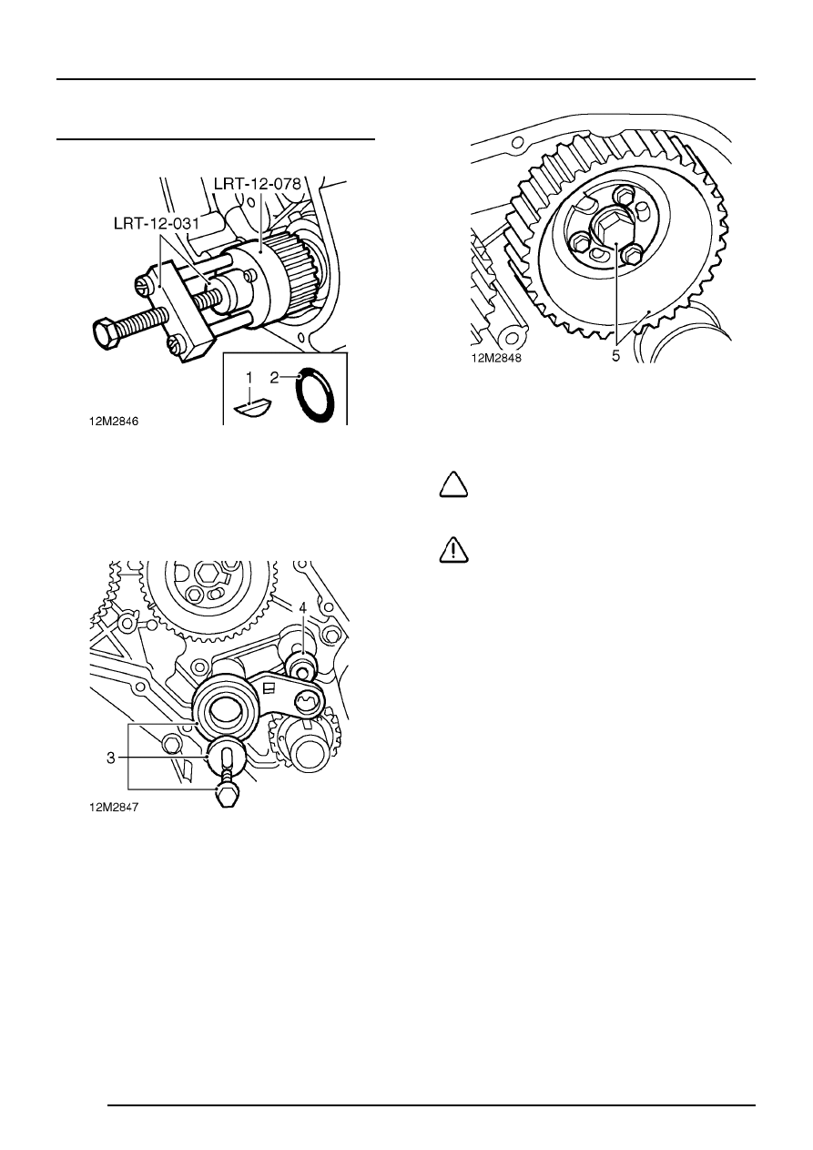
Timing belt tensioner and timing gears - remove

1. Remove crankshaft gear using tools

LRT-12-031 and LRT-12-078, recover
Woodruff key from crankshaft.

2. Remove and discard ’O’ ring.

3. Remove bolt and slotted washer securing

timing belt tensioner pulley, remove pulley
together with tensioner bracket.

4. Recover flanged spacer from idler pulley stud.

5. Remove centre bolt and washer securing

camshaft timing gear, remove gear and hub
plate as an assembly.

NOTE: Later engines are fitted with a
flange head bolt.

CAUTION: Do not remove 3 bolts securing
hub plate to gear.

ENGINE

OVERHAUL

5

6. Remove 3 bolts securing fuel injection pump

gear and hub plate to pump hub.

CAUTION: Do not remove nut securing
hub to fuel injection pump.

7. Remove timing pin LRT-12-045.
8. 
Remove fuel injection pump gear and hub

plate.

Inspecting components

1. Check timing gear teeth for burrs.
2. Remove all traces of gasket from timing belt

front and rear covers using suitable gasket
removal spray and a plastic scraper.

ENGINE

6

OVERHAUL

Timing belt tensioner and gears - refit

1. Smear a new ’O’ ring with engine oil and fit to

crankshaft.

2. Fit Woodruff key in slot in crankshaft.
3. Fit crankshaft gear on to crankshaft and using

a soft mallet, tap gear fully home.

4. Position camshaft timing gear and hub plate to

camshaft, fit bolt and washer, finger tighten
bolt. Do not tighten bolt at this stage.

NOTE: Later engines are fitted with a
flange head bolt.

5. Position fuel injection pump gear and hub plate

to fuel injection pump hub ensuring that cut-out
in hub plate is aligned with timing pin hole in
pump hub.

6. Fit 3 bolts, position slots in gear mid-way under

bolt heads, lightly tighten bolts.

CAUTION: Do not fit bolts through
elongated slots in hub plate. Ensure gear
does not move as bolts are tightened.

7. Insert timing pin LRT-12-045 in hub plate and

injection pump hub. If timing pin cannot be
inserted, slacken bolts and rotate gear until pin
can be fitted, lightly tighten bolts.

ENGINE

OVERHAUL

7

8. Position flanged spacer on idler pulley stud.
9. Fit timing belt tensioner pulley and bracket

ensuring that hole in tensioner bracket is
located on flanged spacer.

10. Fit slotted washer with the slot vertical and fit

bolt, finger tight.

11. Temporarily fit crankshaft pulley bolt to

crankshaft.

NOTE: Flywheel illustrated

12.

Manual gearbox: Rotate crankshaft clockwise
using crankshaft pulley bolt until tool
LRT-12-044 can be inserted in slot in flywheel.

13.

Automatic gearbox: Rotate crankshaft
clockwise using crankshaft pulley bolt until tool
LRT-12-044 can be inserted in slot in drive
plate.

14. Check that crankshaft Woodruff key is aligned

with arrow on timing belt rear cover.

15. If necessary, rotate camshaft timing gear using

the centre bolt until timing mark on gear is
aligned with timing mark on timing belt rear
cover.

16. Remove crankshaft pulley bolt.


Content   ..  4  5  6  7   ..