Range Rover Classic. Manual - part 166


  Index      Land Rover     Range Rover Classic - service manual 1995 year


Search            


Content   ..  164  165  166  167   ..


Range Rover Classic. Manual - part 166


HEATING AND VENTILATION

7

REPAIR

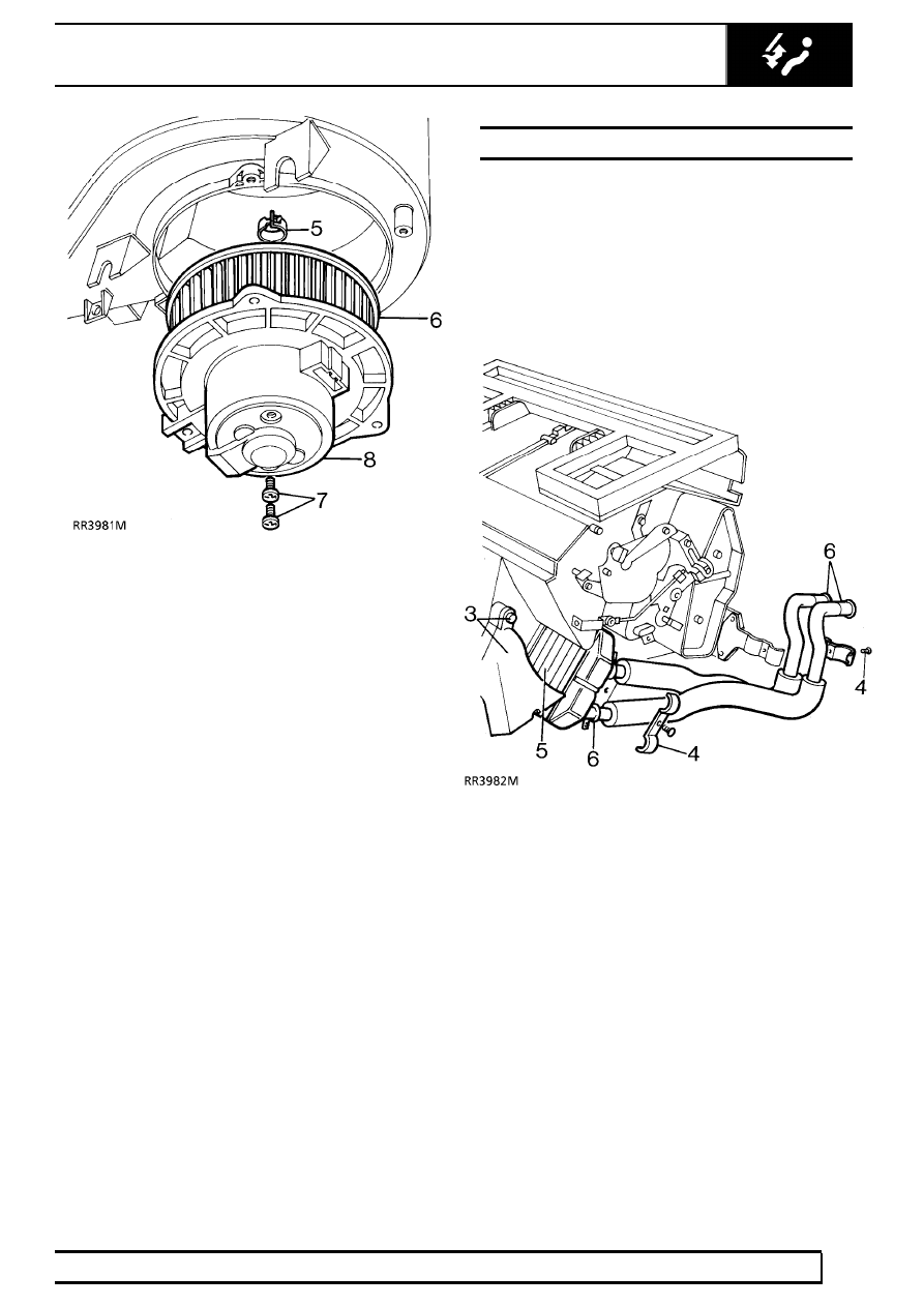
5. Remove fan retaining clip.
6. Remove fan.
7. Remove 2 screws securing motor to casing.
8. Remove blower motor.

Refit

9. Reverse removal procedure.

HEATER MATRIX

Service repair no - 80.20.29

Remove

1. Remove heater unit.

See AIR CONDITIONING,

Repair, Heater and Cooler Unit

2. Remove evaporator.

See AIR CONDITIONING,

Repair, Evaporator and Expansion Valve

3. Remove 2 screws and remove RH side footwell

outlet.

4. Remove heater pipe clips.
5. Slide heater matrix from casing.
6. Release 2 clips and remove 2 heater pipes from

matrix.

Refit

7. Reverse removal procedure.

HEATING AND VENTILATION

1

SPECIFICATIONS, TORQUE

TORQUE VALUES

NOTE: Torque wrenches should be regularly checked for accuracy to ensure that all fixings are
tightened to the correct torque.

Nm

METRIC

M5

6

......................................................................................................

M6

9

......................................................................................................

M8

25

.....................................................................................................

M10

45

...................................................................................................

M12

90

...................................................................................................

M14

105

..................................................................................................

M16

180

..................................................................................................

UNC / UNF

1/4

9

......................................................................................................

5/16

24

...................................................................................................

3/8

39

.....................................................................................................

7/16

78

...................................................................................................

1/2

90

.....................................................................................................

5/8

136

....................................................................................................

Torque values above apply to all screws and bolts used unless otherwise specified.

AIR CONDITIONING

1

DESCRIPTION AND OPERATION

AIR CONDITIONING SYSTEM COMPONENTS

1. Compressor
2. Condenser
3. Receiver/drier
4. Evaporator

5. High pressure servicing connection
6. Low pressure servicing connection
7. Dual pressure switch
8. Sight glass

82

AIR CONDITIONING

2

DESCRIPTION AND OPERATION

SCHEMATIC LAYOUT OF THE AIR CONDITIONING
SYSTEM

1. Compressor
2. Condenser
3. Receiver/drier
4. Thermostatic expansion valve
5. Evaporator
6. Capillary tube
7. Dual pressure switch
8. Cooling fans to maintain air flow
9. Compressor high pressure relief valve

10. Sight glass - refrigerant
11. Drying agent - receiver/drier
12. Blower motor

A1

Ambient air flow through condenser

A2

Ambient air flow through fan and evaporator

A3

Cooled air flow to vehicle interior

F1

High pressure high temperature refrigerant
vapour

F2

High pressure slightly subcooled refrigerant
liquid

F3

High pressure slightly subcooled refrigerant
liquid with moisture, vapour bubbles and foreign
matter removed

F4

Low pressure low temperature mixed liquid and
vapour

F5

Low pressure slightly superheated refrigerant
vapour


Content   ..  164  165  166  167   ..