Range Rover Classic. Manual - part 156


  Index      Land Rover     Range Rover Classic - service manual 1995 year


Search            


Content   ..  154  155  156  157   ..


Range Rover Classic. Manual - part 156


CHASSIS AND BODY

47

REPAIR

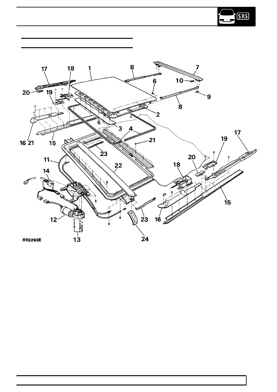
METAL SUNROOF ASSEMBLY

KEY

1. Roof panel
2. Sunroof headliner
3. Insulation pad
4. Roof seals (front and rear)
5. Sunroof headliner retaining clips (quantity - 6)
6. Roof panel retaining screws (quantity - 6)
7. Water channel
8. Water channel connectors
9. Support bracket-water channel

10. Slide shoe-water channel
11. Motor bracket/guide tube assembly
12. Operating motor

13. Motor retaining screws
14. Relay
15. Lower guide rails
16. Front guide rails
17. Slide mechanism
18. Rear guide
19. Pivot bracket
20. Slide shoe
21. Rear edge trim finisher
22. Wind deflector assembly
23. Wind deflector operating arms
24. Support bracket (quantity - 6)

76

CHASSIS AND BODY

48

REPAIR

OPERATION

Sunroof operation is a tilt and slide action controlled
by a rocker switch adjacent to roof lamp, with ignition
switched ’ON’.

1. Depress front of switch to lift rear edge of

sunroof into ’Tilt’ position.

2. Depress rear edge of switch to close roof.
3. Depress rear of switch to slide sunroof into

’Open’ position.

4. Depress front of switch to slide sunroof into

’Close’ position.

NOTE: The electric drive cuts out
automatically in closed, tilt and open
positions. If switch is operated in wrong

direction in one of these positions, press switch
once to reset and again to operate.

EMERGENCY OPERATION

If the sunroof fails to operate, check fuse. To close,
carry out following procedure:

1. Lower interior lamp mounting panel by releasing

two turnbuckles.

2. Remove emergency handle from vehicle tool kit.
3. Engage handle in motor drive spindle and turn to

close roof.

MAINTENANCE

At each service water test drain tubes to ensure they
are not blocked or kinked. Blow air up rear drain tubes
which are clipped to rear mud flap supports. Blow
down front drain tubes which run down ’A’ post and
out of engine bay.
Annually: Clean sunroof opening thoroughly.

NOTE: When vehicle is operated in
extremely dusty conditions more frequent
cleaning is recommended.

OPERATING MOTOR, MICRO-SWITCH AND
RELAY

NOTE: The motor drive spindle retaining
nut is set to correct torque value. If roof
fails to operate check retaining nut torque.

Tighten to

5Nm.

Remove

1. Ensure sunroof is closed. Disconnect battery

negative lead.

2. Remove interior lamp mounting panel to gain

access to motor.

3. Disconnect two wiring connectors.
4. Remove three securing screws and withdraw

motor.

5. Remove screw and withdraw relay.
6. Remove microswitch from motor by drilling out

rivets, if required.

Refit

7. Secure new microswitch using nuts and bolts to

replace rivets. Tighten nuts and apply a spot of
paint to threads.

8. Ensure motor is in ’park’ position, ie. hole on

driven gear aligned with drive spindle.

9. Reverse removal procedure.

10. Check operation of sunroof in all positions.

CHASSIS AND BODY

49

REPAIR

SUNROOF PANEL SEALS

Service repair no - 76.82.55

Remove

1. Position sunroof in tilt position and Disconnect

battery negative lead.

2. Unclip sunroof headliner from roof panel front

and slide headliner back.

3. Remove three roof panel screws from each side

and remove panel.

4. Remove both seals from roof panel.

Refit

5. Fit front seal to front edge of panel. Ensure there

is an equal length of seal each side of centre
point.

6. Butt rear seal against front seal fit tight around

panel edge. Trim excess seal to produce a close
joint with front seal.

7. Refit sunroof panel.

SUNROOF ASSEMBLY

Service repair no - 76.82.71

Including roof panel. Slide mechanism. Wind
deflector. Motor mounting bracket. Guide tubes.

Remove

NOTE: Remove vehicle headlining ONLY if
removing motor mounting bracket and
guide tubes.

See Headlining

1. Partially open sunroof and unclip sunroof

headliner from roof panel front. Slide sunroof
headliner back.

2. Move sunroof to tilt position. Disconnect battery

negative lead.

3. Remove three roof panel screws from each side

and remove panel.

4. Remove motor screws and withdraw motor.

5. Remove guide rail screws, seven each side.
6. Remove pivot bracket and remove front guide

rail.

7. Remove slide and tilt mechanism with flexible

drive cable from both sides. Only disassemble if
replacement parts are required.

76

CHASSIS AND BODY

50

REPAIR

8. Unclip both wind deflector operating arms from

rear mounting brackets. Remove arms from
deflector, if required.

9. Remove seven screws, and withdraw wind

deflector.

10. Remove lower guide rails and rear edge finisher,

seven screws.

11. Remove screws from guide tubes, two each

side. Remove five screws and withdraw motor
mounting bracket.

12. Pull sunroof headliner assembly forward and

remove.

Refit

NOTE: During assembly lightly lubricate
all sliding parts using a silicon spray.

13. Position motor bracket and guide tube assembly.

Fit and tighten securing screws.

14. Position right guide rail in rear retaining bracket.

Push rearwards fully and locate leading edge
under drive cable opening. Repeat operation for
left hand guide rail.

15. Align fixing holes, and loosely fit screw in

seventh hole from front.

16. Position finisher to rear edge of sun roof opening

and secure using seven screws.

17. Position sunroof headliner assembly into outer

guide runners, and push fully rearwards.

18. Lubricate drive cables. Ensure slide and tilt

mechanism is fully assembled.

19. Push cable fully into right side guide tube. Loop

remaining cable and enter rear end into right
inner side runner.

20. Repeat operation 19. for left side. Push both

assemblies rearwards to take up slack in cables,
and push a further 75 mm to rear.

21. Position both front guide rails, aligning with four

forward holes. Fit screws, do not tighten.

22. Position both pivot brackets, loosely fit screws.
23. Fit wind deflector and tighten fixings.
24. Position right operating arm in locating slot in

deflector. Secure opposite end in frame bracket.
Repeat for left side.

25. Pull right slide and tilt mechanism forward, align

with pivot bracket and secure in position using
setting key. Repeat operation for left side.

26. Tighten screws to guide rails, seven each side.
27. Fit and secure relay.
28. Ensure operating motor is in park position ie.

hole on driven gear aligned with drive spindle. Fit
and secure to mounting bracket.


Content   ..  154  155  156  157   ..