Range Rover Classic. Manual - part 110


  Index      Land Rover     Range Rover Classic - service manual 1995 year


Search            


Content   ..  108  109  110  111   ..


Range Rover Classic. Manual - part 110


FRONT SUSPENSION

1

DESCRIPTION AND OPERATION

INTRODUCTION

Suspension design is a major factor in determining the comfort, safety and performance of any vehicle, but is
particularly significant to 4 wheel drive cross country vehicles. The ideal suspension must allow maximum wheel
travel and axle articulation, and provide good ground clearance without loss of traction or directional stability.

A well designed beam axle layout can embrace all of these qualities and also has the inherent advantage (over
independent systems) of no variation in wheel track or camber angle.

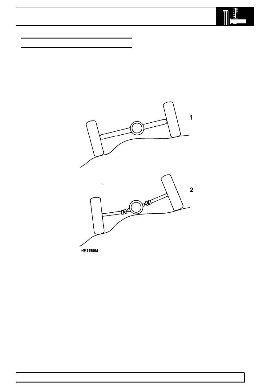
Suspension comparison

1. Beam axle system
2. Independent system

60

FRONT SUSPENSION

2

DESCRIPTION AND OPERATION

AXLE LOCATION

The front axle is controlled longitudinally by two forged steel radius arms and transversely by a panhard rod.

Front axle suspension

1. Panhard rod - transverse location
2. Radius arms - fore aft location
3. Coil springs
4. Shock absorbers

Long travel coil springs and hydraulic shock absorbers, provide the springing for each wheel.

FRONT SUSPENSION

1

REPAIR

SELF LOCKING NUTS

WARNING: Where self locking nuts are
removed, they must be replaced with new
nuts of same specification.

PANHARD ROD

Service repair no - 60.10.07

Remove

WARNING: Air suspension vehicles:
Depressurise system before commencing
work.

See AIR SUSPENSION, Adjustment,

Depressurise System

1. Remove fixings at mounting arm.
2. Remove fixings at axle bracket.
3. Remove Panhard rod.
4. Press out flexible bushes. Ensure the steel

tubing locates on the outer edge of the bush and
not on the rubber inner.

Refit

5. Fit replacement bushes.

CAUTION: Apply pressure to outer edge of
bush, and not rubber inner.

6. Reverse removal procedure. 1 to 4. Tighten

fixings to

88Nm

NOTE: Air suspension vehicles:
Repressurise system

RADIUS ARM

Service repair no - 60.10.16

Remove

WARNING: Air suspension vehicles:
Depressurise system before commencing
work.

See AIR SUSPENSION, Adjustment,

Depressurise System

1. Loosen road wheel retaining nuts.
2. Raise front of vehicle. Support chassis on stands

and remove wheel.

3. Support front axle weight with jack.

4. Remove radius arm to chassis side member

fixings.

5. Disconnect track rod at ball joint.

60

FRONT SUSPENSION

2

REPAIR

6. Remove fixings, radius arm to axle.
7. Lower radius arm front end to clear axle and

remove from vehicle.

8. Press out flexible bushes.

Refit

9. Press in replacement bushes.

CAUTION: When pressing in new bushes
press on outer edge of bush and not
rubber inner.

10. Reverse removal procedure. 1 to 7. Tighten

fixings to following torques:
Radius arm to chassis

175Nm.

Radius arm to axle

200Nm.

NOTE: Air suspension vehicles:
Repressurise system

FRONT SHOCK ABSORBER

Service repair no - 60.30.02

NOTE: Air suspension vehicles:

See AIR

SUSPENSION, Repair, Front Damper

Remove

1. Loosen road wheel retaining nuts.
2. Support chassis on stands and remove road

wheel.

3. Support axle weight with jack.

4. Remove shock absorber lower fixing and

withdraw cupwasher, rubber bush and seating
washer.

5. Remove four shock absorber bracket fixings.


Content   ..  108  109  110  111   ..